
How should you approach parametric road modeling in SketchUp?
Start with a continuous centerline and an explicit cross-section. Coordinate lane widths, kerbs, footpaths and intended levels, then inspect junction continuity and surface transitions after generation. Lizark Roads Pro supports site-modeling workflows; the generated geometry still needs project-specific civil and standards review.
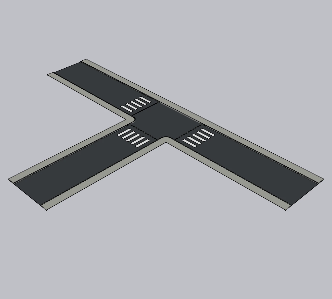
Review the generated T junction in Perspective. Distinguish the carriageway, kerbs, footpaths and crossing markings.
- Inspect the carriageway through the junction.
- Follow the kerb around the corner and look for continuity.
- Crossing markings are modeled geometry; their position still needs project-specific review.
Checkpoint: Check continuity at the junction and review dimensions separately; appearance does not establish engineering compliance.
About this capture
Fresh Lizark Roads Pro Draw-generated demonstration geometry, located separately from the building. Captured live in SketchUp 2026 on October 12, 2026. Numbered markers are page annotations; original pixels are preserved.
Architecture does not stop at the building footprint. Master plans, villa compounds, industrial campuses, and housing layouts all need roads that connect, drain, and comply with local standards. Yet many SketchUp users still model those roads by hand-extruding rectangles, offsetting edges, and praying the curves look right.
There is a better way. Parametric road design treats the road centerline as a single source of truth. Change the centerline and the carriageway, footpath, kerb, drainage strip, lane markings, and junction geometry update together. This article explains the concepts, the standards that matter, and how to apply them inside SketchUp using a parametric road plugin such as Lizark Roads Pro.
Answer-First Summary
TL;DR
- Parametric roads use a centerline + cross-section as the source of truth, not loose faces.
- Every road has a horizontal alignment (plan) and a vertical alignment (profile) that control geometry and drainage.
- Corridor components include carriageway, shoulder/footpath, kerb, verge, and drainage fall.
- Lizark Roads Pro builds these elements along a path, curved or straight, inside SketchUp.
- Always check generated geometry against local codes-like IRC or AASHTO-before issuing drawings.
1. Why architects should care about parametric roads
Not every SketchUp user is a highway engineer. But site plans produced by architects still affect traffic safety, stormwater runoff, and construction cost. A road that is too narrow, too steep, or poorly graded becomes a coordination problem with the civil engineer. Modeling the road parametrically early gives three advantages:
- Design exploration: test multiple circulation schemes without redrawing kerbs and offsets.
- Coordination: share consistent centerline geometry with surveyors and civil consultants.
- Visualization: produce accurate context models for client presentations and authority submissions.
Parametric design is also the only realistic way to handle change. When the client moves a building pad or the planner shifts an access point, a manually modeled road requires hours of cleanup. A parametric road requires one centerline edit.
2. The two alignments every road needs
Road design is built on two alignments. Together they define where the road goes in plan and how it behaves in section.
2.1 Horizontal alignment (plan geometry)
The horizontal alignment is the road centerline seen from above. It is composed of tangents (straight sections) joined by curves. Civil standards define minimum curve radii based on design speed, super-elevation, and vehicle class. For architectural site roads, the curve radius is often driven by fire tender turning requirements rather than highway speed.
A clean SketchUp path for parametric road generation should have these qualities:
- Continuous edges without breaks or micro-segments.
- Curves that are true arcs or smooth splines, not faceted polylines.
- A consistent start and end direction so lane markings and junctions align.
2.2 Vertical alignment (profile)
The vertical alignment is the road centerline seen from the side. It controls grade, crest curves, sag curves, and drainage. Even a flat-looking site drawing hides elevation changes. Without a profile, the road may slope the wrong way, trap water, or conflict with the finished floor level of buildings.
In SketchUp parametric workflows, the vertical alignment is usually represented by z-values along the path or by a top-of-road profile supplied by the surveyor. The key parameters are:
- Gradient: the longitudinal slope, typically 0.5%-5% for site roads.
- Crest and sag curves: vertical curves at grade changes to maintain sight distance.
- Cross-fall: the transverse slope that drains water to the kerb or channel.
3. From centerline to corridor
A corridor is the 3D strip of land occupied by the road, including all of its components. Once the horizontal and vertical alignments exist, the corridor is generated by sweeping a cross-section along the path. The cross-section defines widths, heights, and slopes at each offset from the centerline.
A typical low-speed site road cross-section might include:
- Carriageway: the paved running surface, often 3.0-7.0 meters wide depending on traffic.
- Kerb and channel: separates the carriageway from the verge and directs runoff.
- Footpath or shoulder: pedestrian or stopping lane, set slightly above the drainage path.
- Verge/landscape strip: green buffer that absorbs runoff and hides utilities.
- Drainage fall: cross-fall toward channels or gullies, usually 2.0-2.5%.
Manual modeling of all these elements is tedious because each curve requires correct offset, fillet, and height relationships. Parametric road plugins handle the offsets automatically and rebuild them when the centerline changes.
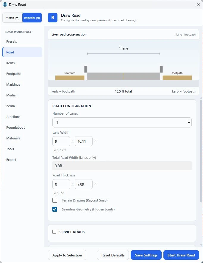
Open Draw Road and choose explicit units. Set the lane count and lane width, then inspect the cross-section preview before drawing.
- The active units are Imperial; switch units deliberately when needed.
- Set the lane count before interpreting total lane width.
- The live preview separates lanes from kerb and footpath space.
Checkpoint: The lane count, units and preview should describe your intended project cross-section.
About this capture
This configuration capture shows a separate one-lane example. The T-junction review geometry uses its own two-lane recipe; these are not construction recommendations. Captured live in SketchUp 2026 on October 12, 2026. Numbered markers are page annotations; original pixels are preserved.
4. How Lizark Roads Pro implements this inside SketchUp
Lizark Roads Pro is designed to bring corridor thinking into SketchUp without requiring a separate civil engineering package. It works on top of native SketchUp paths, edges, and groups, so the generated geometry stays inside your model rather than being locked in an external file.
4.1 Path import and node editing
You can draw a centerline directly in SketchUp or import a path from a CAD survey. Node editing lets you drag control points, adjust curve radii, and snap to existing site geometry. Because the road is bound to the path, any geometry update follows.
4.2 Lane and shoulder offsets
The plugin applies left and right offsets based on your cross-section inputs. You define carriageway width, shoulder width, and kerb offset. Curved sections automatically account for inner/outer edge geometry.
4.3 Junctions, roundabouts, and crossings
Roads rarely run as isolated strips. Lizark Roads Pro includes junctions, connections, pedestrian crossings, and roundabout primitives. These elements trim the approaching corridors and generate turning geometry that follows the same parametric rules.
4.4 Road furniture and signage
Placing signs, street lights, and bollards along a centerline can be done by spacing components parametrically. Change the path and the furniture relocates. This is especially useful for long access roads or campus drives where repeated elements are common.
5. Standards to know and follow
Parametric generation does not replace engineering judgment. Local codes still govern sight distance, gradient, curve radius, and drainage. Depending on your region, the relevant references usually include one of the following:
- IRC (Indian Roads Congress) guidelines for geometric design and rural roads in India.
- AASHTO A Policy on Geometric Design of Highways and Streets used widely in North America.
- Local municipal bylaws that set fire-lane widths, parking bay dimensions, and pedestrian clearances.
Use these standards to set your cross-section inputs before generating geometry. For example, if the IRC recommends a minimum curve radius for your design speed, enter that radius as a constraint in the plugin. The generated model then becomes a starting point for detailed civil review rather than a guess.
6. A real-world site-road workflow
Here is a practical sequence that architectural teams can follow for medium-scale site projects. Adjust the detail based on project complexity.
- Import the survey at the correct scale and lock it as a reference.
- Mark building footprints and key site levels first so the road serves them.
- Sketch the centerline as the proposed circulation spine, using true arcs for curves.
- Assign levels to the centerline vertices from the finished levels plan.
- Define the cross-section including carriageway, kerb, footpath, and verge widths.
- Generate the corridor and place it on its own tag or group.
- Add junctions, crossings, and signs at conflict points.
- Check drainage visually by turning on hidden geometry and inspecting the cross-fall.
- Iterate with the client or civil consultant using the live centerline.
- Export the final centerline and corridor for CAD coordination.
This workflow keeps the road model alive through design changes. It also gives you something meaningful to show early: a credible site circulation study that responds to edits in minutes rather than days.
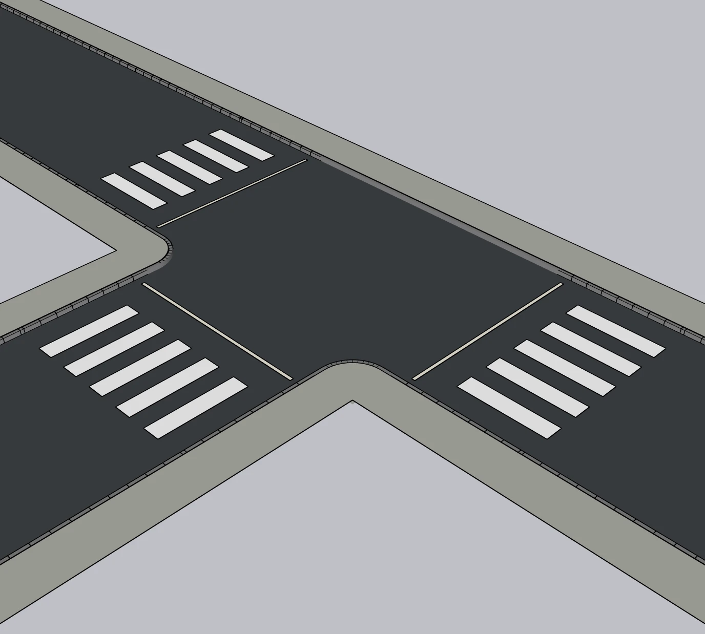
Review a close-up of the junction after generation. Follow the kerb transition and inspect crossing boundaries at each approach.
- Inspect the joined carriageway surface.
- Follow the curved kerb into the adjoining straight segment.
- Review crossing footprints against the intended approach geometry.
Checkpoint: Record gaps, overlaps or unwanted surface steps before preparing a coordination handoff.
About this capture
Fresh Perspective detail of the same generated T junction; it is a visual inspection example, not a road-design certification. Captured live in SketchUp 2026 on October 12, 2026. Numbered markers are page annotations; original pixels are preserved.
7. Common pitfalls
Parametric road generation is powerful, but it can still produce bad results if inputs are sloppy. Watch for these issues:
- Disconnected paths: Junctions must connect to a continuous network; otherwise offsets misalign.
- Extreme gradients: A visually flat centerline can hide a 12% grade if z-values are wrong.
- Too-tight curves: Small-radius curves cause self-intersecting offsets if the cross-section is wider than the curve allows.
- Ignoring superelevation: On curved roads, the cross-section needs to bank; a flat extrusion will not drain.
- Layers ignored: Keep roads on dedicated tags so the generated geometry does not fight with topography.
8. Integration with building models
Road design is most valuable when it is connected to the building model. If you use Lizark for the buildings, keep the road model in the same SketchUp file or a linked component. This lets you check building approach levels, sight lines from parking, and service-vehicle access before the design is finalized.
Use the same tagging convention for both: X_Roads, X_Buildings, X_Topography, and X_Setout. Scenes can then isolate roads for review, exports, or presentation.
9. Conclusion
Parametric road design is not a civil-engineering-only discipline. It is a planning discipline. Any architect producing site layouts in SketchUp benefits from treating roads as data-driven corridors rather than hand-drawn shapes. The payoff is faster iteration, cleaner coordination with consultants, and a site model that holds together when the client changes their mind.
Start with the centerline, define a standards-based cross-section, generate the corridor, and verify it against local codes. Plugins like Lizark Roads Pro turn that sequence from a multi-day task into a same-day design exploration.
References and further reading
- Indian Roads Congress (IRC). IRC:SP:73-2015 - Manual of Specifications & Standards for Two Laning of Highways and related geometric design guidelines. https://www.irc.nic.in
- AASHTO. A Policy on Geometric Design of Highways and Streets (Green Book). https://www.aashto.org
- ISO (2018). ISO 19650-1:2018 - Organization and digitization of information about buildings and civil engineering works, including building information modelling (BIM).
- SketchUp Help Center. Drawing arcs and curves. https://help.sketchup.com
Want to see how roads and buildings fit together in one model? Browse the Lizark Roads Pro and Lizark pages, or visit the tutorial library for step-by-step guides.