
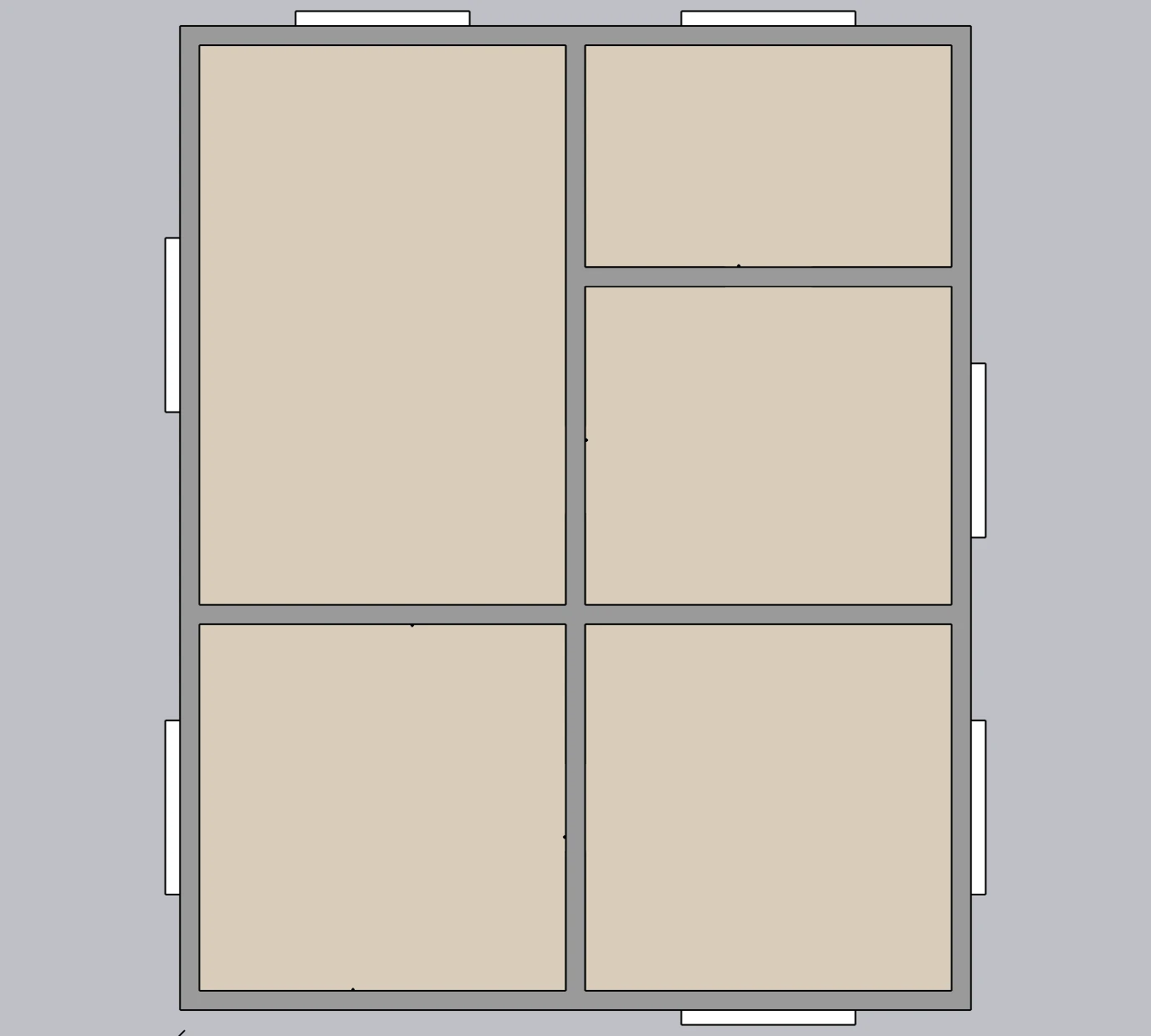
How do you prepare plans, sections and elevations from SketchUp?
Use saved scenes to coordinate camera, section cuts, visibility and styles. Use orthographic views for scaled drawings and Perspective for spatial review. Verify scale and dimensions in the exported deliverable or LayOut viewport. A Top view alone is not a section-cut floor plan.
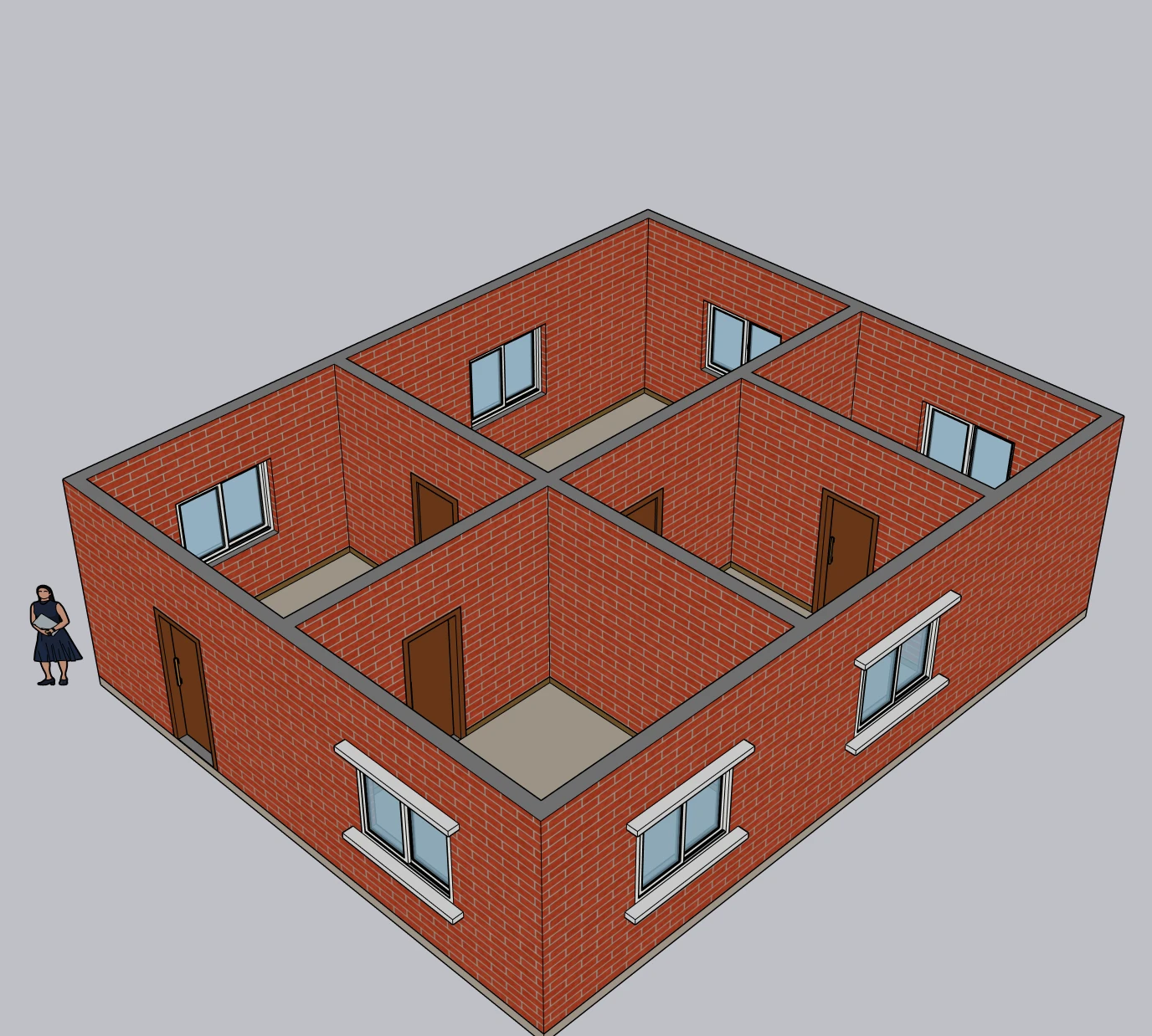
Inspect the accepted model in Perspective before setting up drawing views. Identify which conditions need a plan, section or elevation.
- A junction may need a section to explain its vertical relationship.
- An opening needs its position checked in plan and its height checked in section or elevation.
- Floor relationships should be represented consistently across the view set.
Checkpoint: Do not use Perspective as a substitute for a scaled orthographic drawing.
About this capture
Perspective is used for spatial review. Roof and parapet are hidden to expose the internal arrangement. Captured live in SketchUp 2026 on October 12, 2026. Numbered markers are page annotations; original pixels are preserved.
The numbered photographs show a separate live Lizark demonstration model. Worked dimensions in the text remain illustrative exercises; the captures are not a measured revision or exchange benchmark.
Build a coordinated view set
To prepare plans, sections and elevations from SketchUp, establish a reliable source model, create named views with intentional camera and visibility settings, and check the resulting drawing scale and annotations. Use the same accepted model revision throughout the view set.
A model view and a drawing sheet serve different purposes. The view describes selected model geometry; the sheet adds scale, labels, dimensions and presentation context. Both need review after a design change.
This guide uses an illustrative small building with a 6,000 × 4,000 mm exterior reference and a 2,700 mm wall height. The dimensions support simple checks. They are not an as-built survey, construction requirement or published project result.
Decide what each drawing must communicate
Choose the required views before adding sheet detail. A plan at the wrong cut height can conceal the very opening you need to explain. An elevation can show exterior appearance while omitting the interior condition that requires a section.
| View | Main question | Example review |
|---|---|---|
| Floor plan | How are spaces and openings arranged? | Partition position, door access and window locations |
| Section | How do vertical relationships work? | Floor, ceiling, wall height, window head and sill |
| Elevation | What does the selected face show? | Openings, exterior composition and visible levels |
| Perspective | How does the arrangement read spatially? | Context and ambiguous junctions |
Use perspectives to support explanation rather than substitute for scaled orthographic views. Establish which drawing is authoritative for each dimension so that contradictory annotations do not remain unnoticed across sheets.
Check the model before setting up views
A clear camera does not repair an incorrect model. Verify the dimensions needed for the drawings, then inspect the relevant floors, walls and openings. Hide references deliberately rather than deleting the evidence used for comparison.
For a Lizark-generated building, apply the same checks as for a manually modeled building. Inspect junctions and opening geometry before arranging drawing views. The Lizark tutorial library covers product-specific modeling actions; this article focuses on coordinating the resulting documentation.
Use the CAD preparation guide if the model’s source scale is uncertain. Use the organization guide if required elements cannot be selected or hidden predictably. These problems are cheaper to resolve before a set of views depends on them.
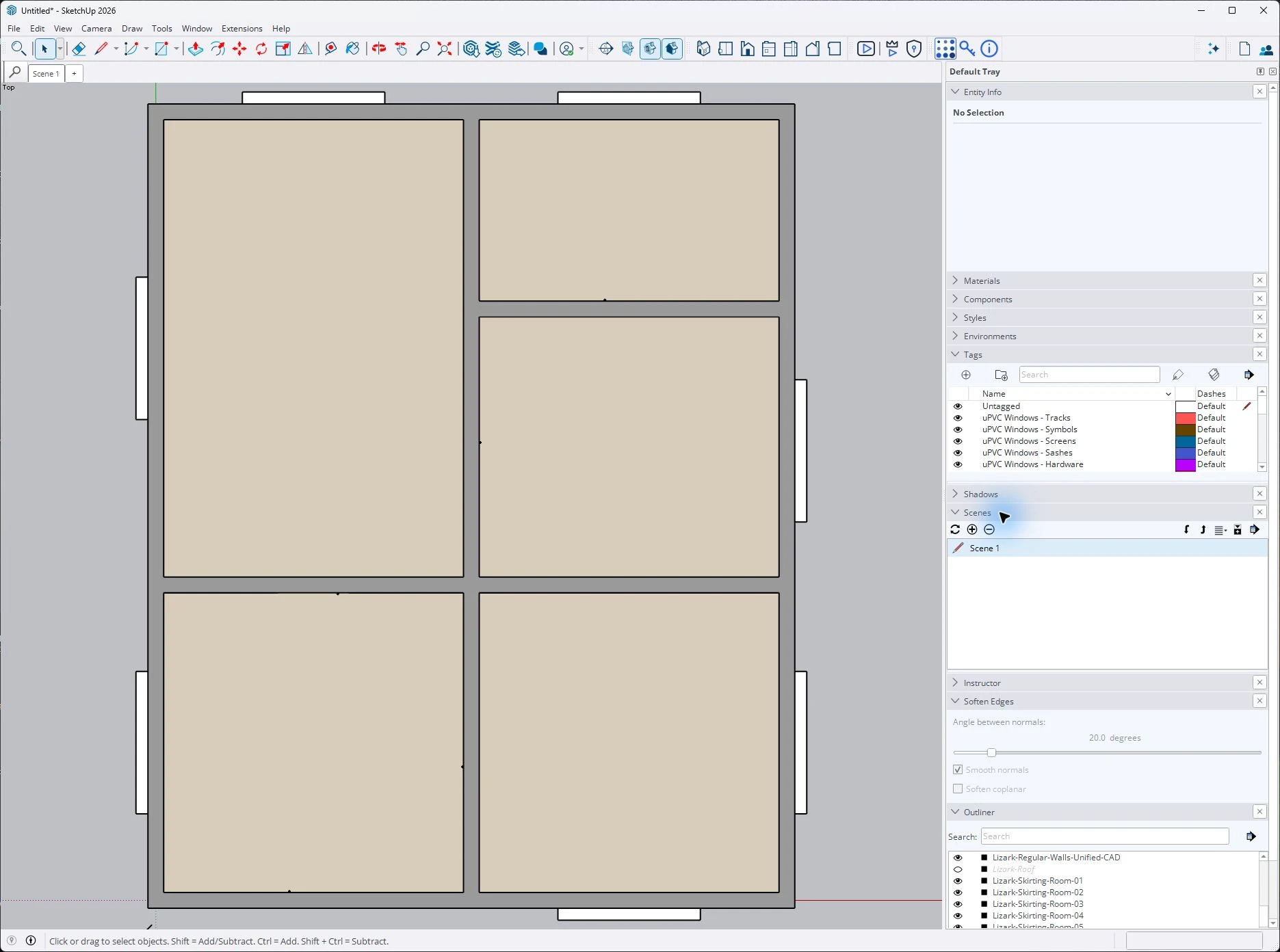
Switch to a top review to compare the outline, then establish the appropriate section cut before issuing a floor plan.
- The gray wall tops describe the outline, not a chosen horizontal cut height.
- Openings below the wall tops are concealed; create the required section view.
- Keep scene identity explicit when creating the drawing-view register.
Checkpoint: These wall tops conceal door openings. A top view alone is not a complete floor plan.
About this capture
The screenshot shows a roof-hidden top view of the generated model, with Scenes and Outliner visible. It is not a section cut or a LayOut sheet. Captured live in SketchUp 2026 on October 12, 2026. Markers are page annotations; original pixels are preserved.
Set up named scenes intentionally
Create a small scene register such as A01_Plan_Level01, A02_Section_AA and A03_Elevation_North. The register should state the intended camera, section condition and visibility set. The naming convention is a proposed office practice, not a SketchUp requirement.
| Scene | Camera intent | Review before saving |
|---|---|---|
| Level 01 plan | Orthographic top view | Correct cut and reference visibility |
| Section A–A | Orthographic view aligned with section | Correct active cut and required objects |
| North elevation | Orthographic face view | Exterior visibility and orientation |
| Review perspective | Spatial inspection | Clearly distinguished from drawing scenes |
SketchUp’s scene guidance explains the properties that can be stored with a scene. Save only the properties that should define the view, and revisit them deliberately when the view needs to change.
Keep a temporary working scene separate from issued drawing scenes. Otherwise, updating a scene after an inspection can unintentionally preserve hidden objects or a changed camera. A scene name is useful only when it continues to describe a stable view intent.
Place and check section cuts
Use a section where it answers a vertical or internal relationship. Place it through the condition you need to explain, then check that nearby objects are represented meaningfully. A cut chosen only because it looks attractive can miss the important junction.
Section behavior also depends on editing context. SketchUp’s section-plane documentation describes the relationship between cuts and contexts. Inspect the actual active cut rather than assuming a visible plane is the one affecting the view.
For the illustrative building, choose a section crossing the revised partition and window. Check the 2,700 mm wall-height reference and the stated sill/head values. Where finishes matter, show their relationship to the core rather than allowing coincident surfaces to hide it.
Link LayOut viewports to the intended scenes
In a LayOut workflow, select the appropriate saved SketchUp scene for each viewport. SketchUp’s LayOut scene-selection documentation describes the available selection methods.
Record the scene identity next to the viewport in your working checklist. Check that the source model file and revision are correct. A properly framed viewport from an older model is still the wrong drawing.
Treat viewport appearance, annotations and model geometry as separate review items. A model change may be represented while an old text label remains. A dimension that looks plausible still needs a reference check, particularly after replacing a model or changing a viewport.
This is a native SketchUp/LayOut documentation workflow. It does not claim that Lizark automatically creates or synchronizes a complete drawing set.
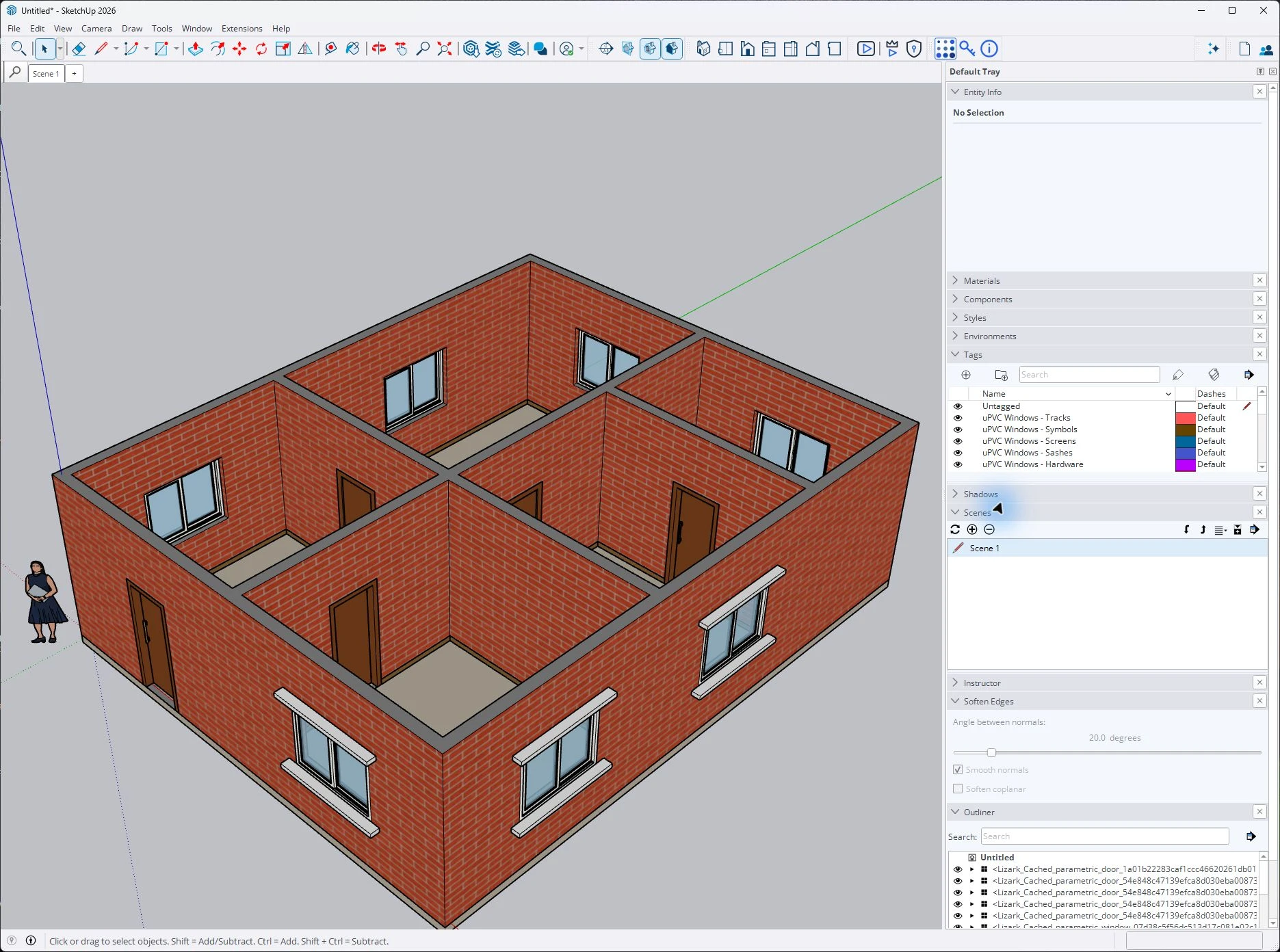
Use the Scenes panel to establish stable view identities. In LayOut, select the intended model scene for each viewport and verify its output scale.
- The tab names the saved scene.
- The scene entry is the view identity to track in your register.
- Review which properties are saved when updating a scene.
Checkpoint: Check the source model revision, scene identity and a known exported dimension.
About this capture
This screenshot demonstrates SketchUp scene controls. LayOut viewport linking and printed scale are explained in the article, not demonstrated by this capture. Captured live in SketchUp 2026 on October 12, 2026. Markers are page annotations; original pixels are preserved.
Verify scale in the exported deliverable
For a drawing at 1:100, a 6,000 mm model reference corresponds to 60 mm on the sheet. At 1:50, it corresponds to 120 mm. Use a known reference to check the actual exported output, not just the scale label printed beside it.
Printing or viewing a PDF with “fit to page” can change the displayed or printed size. Confirm the intended paper size and output settings before measuring. Include a scale bar where useful, but remember that it describes scale only if the output has retained it.
Check both a horizontal and a vertical reference when the drawing’s reliability matters. A screen screenshot is not a dependable substitute for an exported scaled drawing. For CAD handoff, verify export units and inspect the result in the intended receiving workflow.
Recheck the set after a revision
Use the same change brief across the model and sheets. If a window widens, inspect its plan representation, elevation appearance, affected section and annotations. A changed partition may require dimension updates even where it is not cut by the primary section.
Download the drawing-view review checklist. Record the source model revision, scene, scale, reference measurements and annotation status for each view. Leave exceptions explicit before accepting the set.
Documentation questions
Can an elevation replace a section?
Only when it communicates the required condition. Internal vertical relationships generally require a view that actually reveals them.
Is setting a viewport scale enough?
Check a known dimension in the exported output as well. The source view, export and printing process can introduce additional errors.
Does updating the model verify the annotations?
No. Review labels, dimensions and references independently so they describe the accepted revision.