
What should you check before turning a DWG floor plan into a SketchUp model?
Check a known dimension, drawing units, origin and linework before modeling. Keep the imported reference separate from generated geometry, distinguish wall boundaries from opening markers and review junctions. Compare the generated outline and openings against the accepted reference before relying on the model.
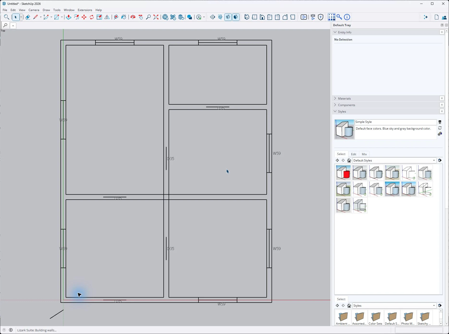
Identify the wall network and opening markers in a plan view. Apply the same inspection to your imported CAD reference before generating a building.
- Follow the outer wall boundary; decide whether your reference describes a face or a centerline.
- Inspect the partition junction before modeling connected walls.
- Opening labels and marker lines identify intended openings; they are not proof of the final cut.
Checkpoint: Distinguish wall boundaries from door and window markers; measure your own known reference dimensions.
About this capture
This is a Lizark-traced demonstration plan, not a screenshot of DWG import or a verified calibration result. Captured live in SketchUp 2026 on October 12, 2026. Numbered markers are page annotations; original pixels are preserved.
The numbered photographs show a separate live Lizark demonstration model. Worked dimensions in the text remain illustrative exercises; the captures are not a measured revision or exchange benchmark.
Start with a trustworthy reference
A reliable DWG-to-SketchUp workflow has three separate jobs: establish trustworthy reference geometry, build an editable model, and verify that the model still agrees with the drawing. Completing an import is only the first checkpoint. A plan can look correct while its dimensions, drawing elevation or wall boundaries are wrong.
This guide is for architectural floor plans, whether you model manually or use Lizark. It uses a small illustrative exercise rather than a claimed client project: a rectangular reference measuring 6,000 × 4,000 mm, one internal partition and a door opening. The arithmetic and acceptance checks are reusable; the example is not a measured automation benchmark.
Keep the received file unchanged. Prepare a working copy and record its drawing number, revision and intended units. That gives you somewhere to return when cleanup removes an entity you later discover was important.
Decide what the source actually contains
DWG and DXF describe drawing entities. A PDF or image can be a useful visual reference, but its appearance does not establish that you have editable wall boundaries. A scanned drawing still needs calibration and interpretation. Even a vector drawing may contain decorative hatching, blocks or annotations that are not building geometry.
| Source condition | Useful first action | Avoid assuming |
|---|---|---|
| DWG with clear wall layers | Prepare a copy containing the relevant plan geometry | Every imported line describes a wall |
| DWG with several plans and details | Isolate the required floor and revision | All visible drawings share one elevation or scale |
| PDF with a printed dimension | Identify a trustworthy dimension and calibrate the reference | The displayed page size is the building scale |
| Scanned image with unclear dimensions | Request a better source or an independent measurement | Tracing can recover missing dimensional information |
For current import options and entity support, consult SketchUp’s CAD import documentation. Confirm the capabilities of your installed SketchUp edition and version before deciding on a file route.
Check scale with two independent dimensions
Measure a known distance after import. Do not use a furniture symbol as your calibration reference: its graphic size may be approximate. Prefer a dimension tied to identifiable building points.
For the illustrative plan, the long edge should measure 6,000 mm. If it measures 6 mm, the correction ratio is 6,000 ÷ 6 = 1,000. The short edge should then measure 4,000 mm. This second check matters because correcting one distance cannot repair a distorted or incorrectly interpreted source.
| Check | Expected in this exercise | Interpretation |
|---|---|---|
| Long reference edge | 6,000 mm | Primary scale check |
| Short reference edge | 4,000 mm | Independent verification |
| Reference rectangle area | 24 m² | Additional arithmetic check, not usable floor area |
| Repeated door symbol | Compare with its stated dimension | Secondary plausibility check only |
Changing the displayed unit format does not prove that the geometry has been resized. Re-measure the reference after any correction. If the two known dimensions disagree, investigate the source rather than averaging them.
Separate linework defects from design intent
A face needs a usable closed boundary in the appropriate editing context. When a region refuses to form a face, diagnose that region before cleaning the entire drawing. A missing face is a symptom, not permission to close every opening.
| Symptom | Question to investigate | Controlled response |
|---|---|---|
| Almost closed corner | Are endpoints actually coincident? | Repair only the unintended break |
| Lines appear connected in plan | Do their elevations differ? | Check the source and flatten the intended 2D reference where appropriate |
| Unexpected narrow strips | Are there duplicates, offsets or finish lines? | Identify which boundaries should drive the model |
| Large empty space around the plan | Is there distant geometry or a required survey origin? | Separate stray entities from necessary coordinates |
| Door gap disappears after cleanup | Was that gap intentional? | Restore the opening reference and revise the cleanup rule |
Inspect a small test region from more than one view. Preserve surveyed coordinates when coordination depends on them; record any deliberate translation instead of silently relocating the project. An architectural cleanup process should remove ambiguity, not erase information needed by another discipline.
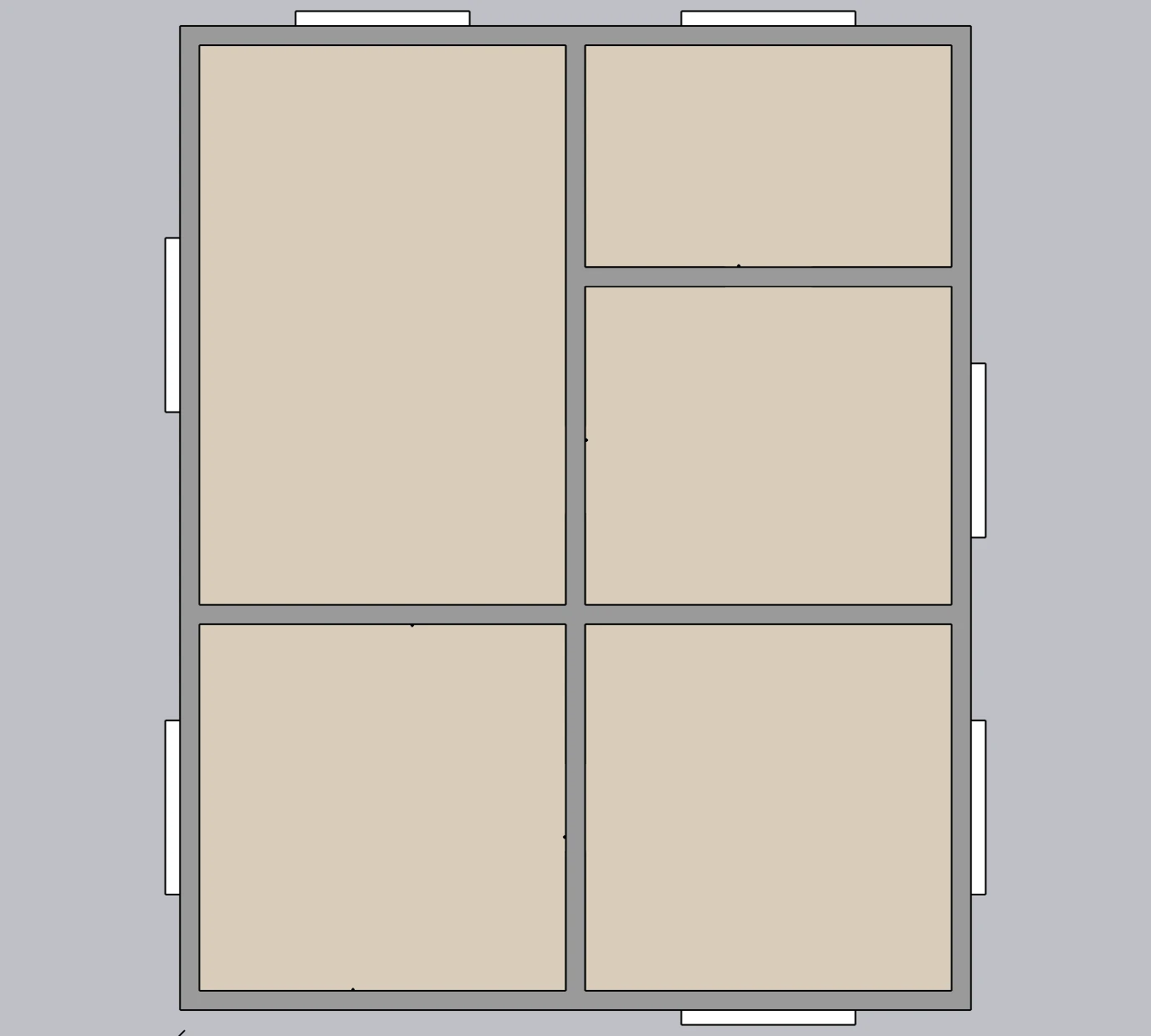
Review the generated building from above with the roof hidden. Compare wall placement and junctions with the source plan.
- Compare this outside corner with the corresponding source corner.
- Review the central wall intersection for continuity.
- Door openings are below these wall tops; this view cannot prove their width or position.
Checkpoint: Check the outline independently. Use a section or Perspective view to inspect openings below wall tops.
About this capture
This is a top review of the generated model. It is not a section-cut floor plan. Captured live in SketchUp 2026 on October 12, 2026. Markers are page annotations; original pixels are preserved.
Keep the reference separate from the model
Put the imported reference in a clearly named container such as REF_Level01_RevA, and keep it separate from modeled walls. Give the reference its own visibility tag and lock it when its alignment is established. Draw new geometry in the intended model context rather than accidentally editing the imported container.
Agree on what each reference line means: structural core, finished face, centerline or symbolic edge. A consistent tracing rule is more useful than guessing separately at every wall. Write down the chosen wall thicknesses and which side of the reference they occupy.
For related organization decisions, use the groups, components and tags guide. Separating the reference also makes it easier to compare a revised drawing later without mixing two revisions into one model.
Introduce Lizark at the modeling stage
Once scale and line meaning are established, follow the Lizark import and 2D-to-3D tutorial for the product-specific sequence. The same reference checks apply whether you use import-based generation, tracing or native SketchUp modeling.
Start with one representative room or wall span. Inspect the resulting wall thickness, height, junctions and openings before expanding the operation. A convincing perspective view is not enough: compare a top view and a section against the source.
Treat an ambiguous door swing, wall return or slab boundary as a design question. Keep that region manual until its meaning is resolved. Lizark can be part of the modeling workflow; it cannot establish the correctness of a source drawing from appearance alone.
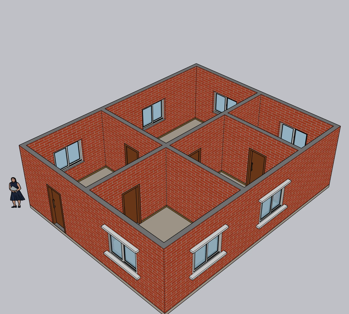
Return to Perspective and inspect representative windows, wall junctions and floor relationships before adding more detail.
- Inspect the partition junction rather than relying on a convincing overall view.
- Check the window frame against its host opening.
- Review floor-to-wall relationships inside a representative space.
Checkpoint: The frame, wall opening and neighboring surfaces must agree when inspected from more than one view.
About this capture
The multi-room example was generated using Lizark Trace Wall, traced opening markers and Generate 3D; roof and parapet are hidden for review. Captured live in SketchUp 2026 on October 12, 2026. Markers are page annotations; original pixels are preserved.
Accept the model with a recorded checklist
Before adding presentation detail, record which reference dimensions passed, which assumptions remain and which drawing revision the model represents. A colleague should be able to repeat your checks without asking where you measured.
Use the CAD preparation checklist to record source units, two dimensions, origin treatment, linework checks and opening review. Leave unresolved items visible rather than treating an empty checklist cell as approval.
When the drawing changes, preserve the accepted reference and bring the new revision into a separate container. Follow the floor plan revision workflow to identify affected objects. This keeps initial conversion and later design changes connected without turning them into the same operation.
Questions worth resolving before modeling
Should every gap be closed?
No. A gap may be a defect, an opening or an intentional break in the drawing convention. Compare it with the source and decide its meaning before editing.
Can a correctly scaled image replace a DWG?
It can serve as a tracing reference when its dimensional reliability is adequate. It does not become editable CAD linework simply because it has been calibrated.
Is successful generation the final quality check?
No. Compare generated geometry with independently checked dimensions and inspect junctions and openings. Save the accepted model before proceeding to finishes or documentation.