
US framing tutorial library · Lizark 1.0.28
US framing tutorials for SketchUp
Follow the numbered screenshots for each building element. Start with the overview or select a specific tutorial, then use the reference below for shared profile and wall controls.
Lizark 1.0.28 · SketchUp 2026
US framing screenshot tutorials
Choose an element and follow the numbered screenshots, example settings and checkpoints. Start with the overview, then build a wall and add a door and window.
No matching tutorials. Try another term or clear the search.
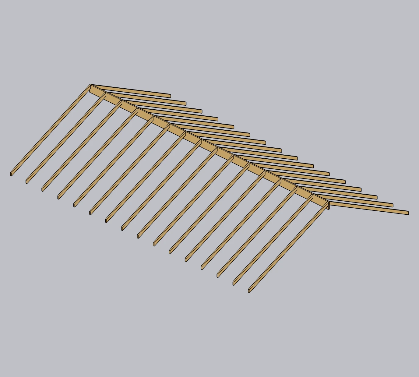
US Framing in SketchUp: Model Homes with Lizark
Model US residential framing in SketchUp with Lizark. Explore wood studs, floor joists and roof rafters, see real model captures, and start your first project.
Follow the tutorial →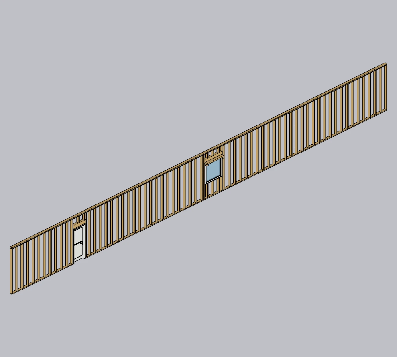
Wood Wall Framing in SketchUp with Lizark
Model US wood wall framing in SketchUp with Lizark. Plan studs, plates, assembly layers and rough openings for residential design reviews and presentations.
Follow the tutorial →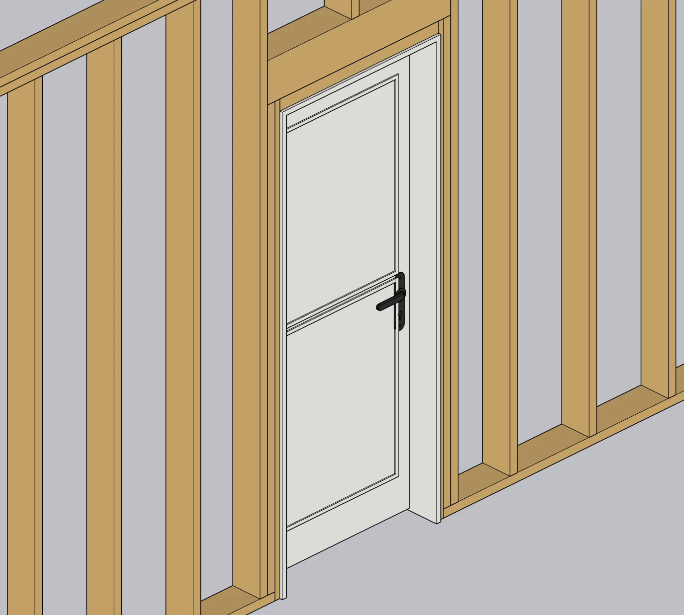
Door Rough Openings in SketchUp with Lizark
Plan door rough openings in SketchUp with Lizark. Coordinate the door unit, wall depth, framing and swing before presenting US residential remodels to clients.
Follow the tutorial →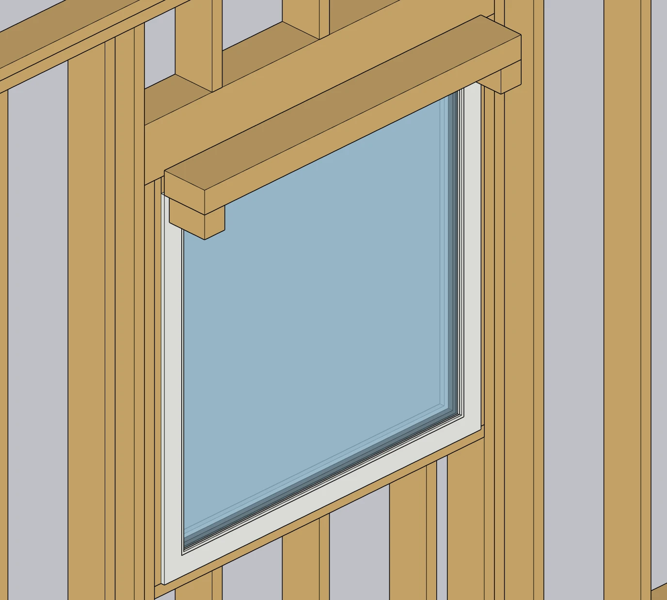
Window Framing in SketchUp with Lizark
Model window framing in SketchUp with Lizark. Coordinate rough openings, sill heights, wall depth and window styles for US home additions and remodel reviews.
Follow the tutorial →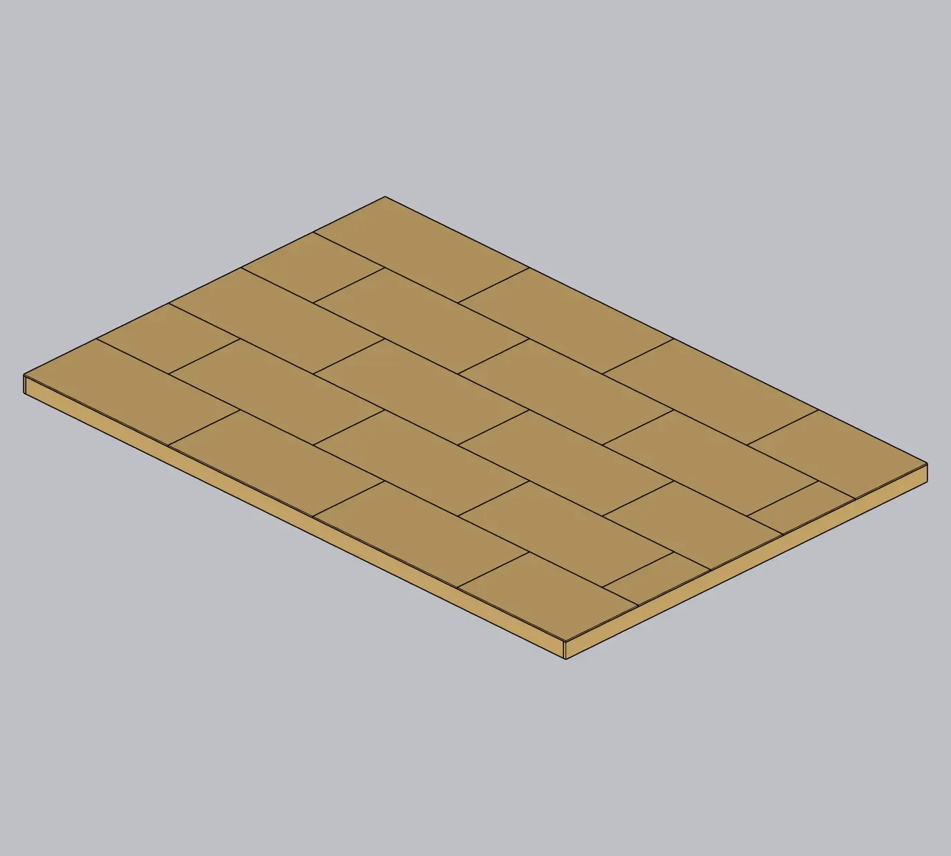
Floor Joist Framing in SketchUp with Lizark
Create floor joist framing in SketchUp with Lizark. Compare joists, I-joists and floor trusses, set elevations and coordinate subfloors in US home models.
Follow the tutorial → Roof Rafter Framing in SketchUp with Lizark
Model roof rafter framing in SketchUp with Lizark. Set pitch, footprint and spacing, and compare gable, shed and hip roof studies for US residential projects.
Follow the tutorial →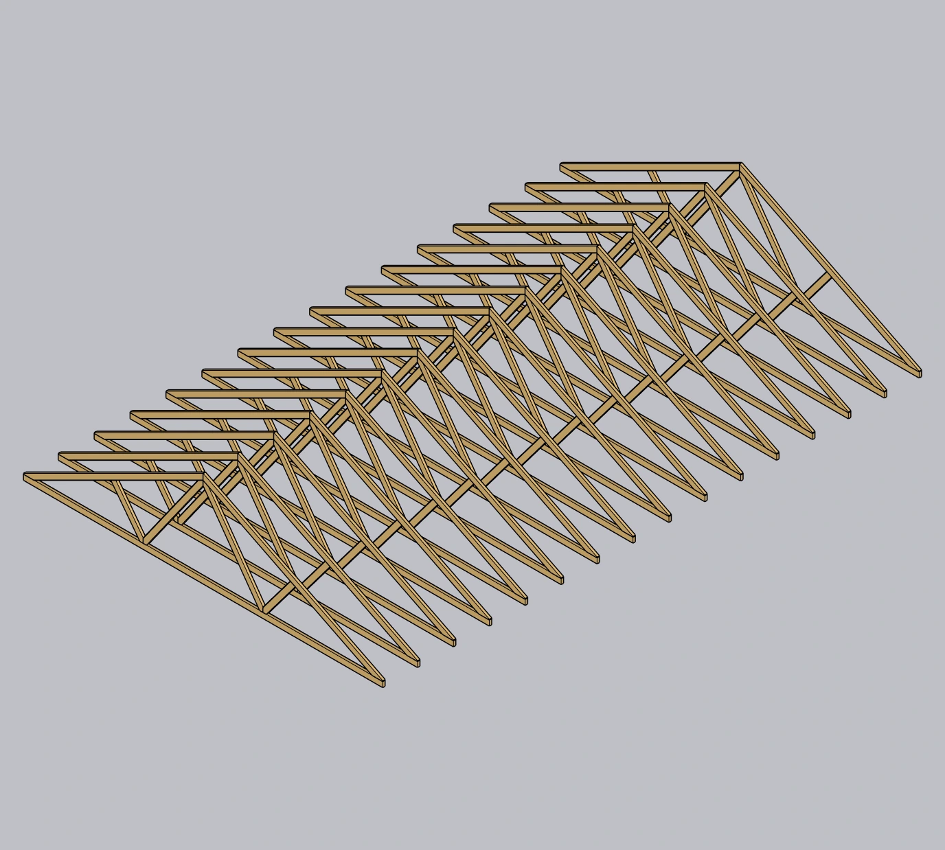
Roof Truss Modeling in SketchUp with Lizark
Plan roof truss models in SketchUp with Lizark. Compare Fink and Howe layouts, coordinate pitch and bearing, and prepare clear US residential framing studies.
Follow the tutorial →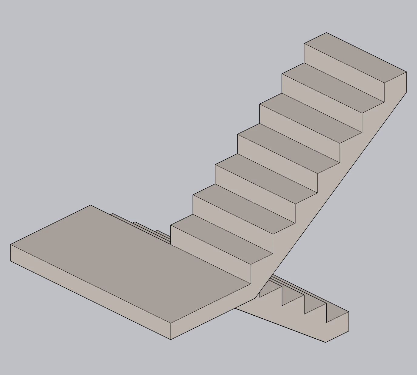
Stair Framing in SketchUp with Lizark
Plan stair framing in SketchUp with Lizark. Coordinate floor heights, treads, risers and landings for straight, L-shaped and dog-leg residential stair studies.
Follow the tutorial →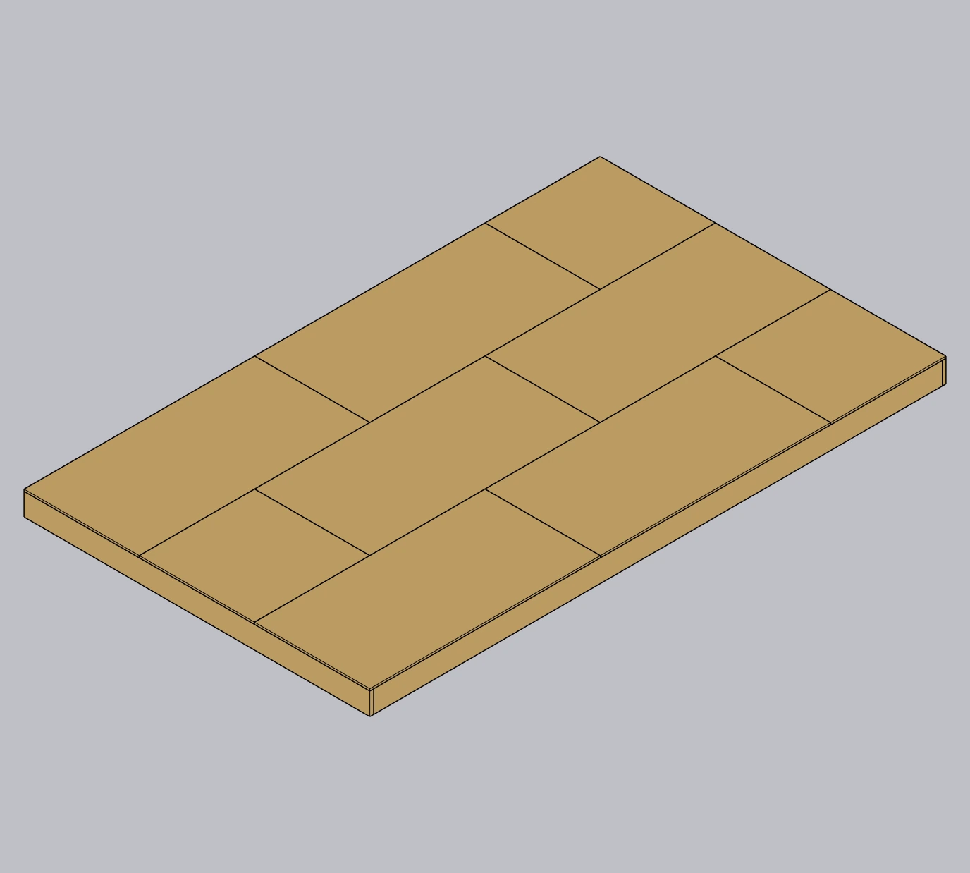
Deck and Porch Framing in SketchUp
Plan deck and porch framing in SketchUp with Lizark. Coordinate joists, beams, posts, stairs and roof relationships for clear US outdoor-living design studies.
Follow the tutorial →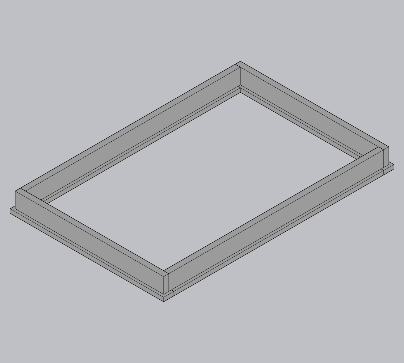
Foundation Modeling in SketchUp with Lizark
Model foundation studies in SketchUp with Lizark. Coordinate slab and stem-wall geometry, elevations and the wall footprint for US residential design reviews.
Follow the tutorial →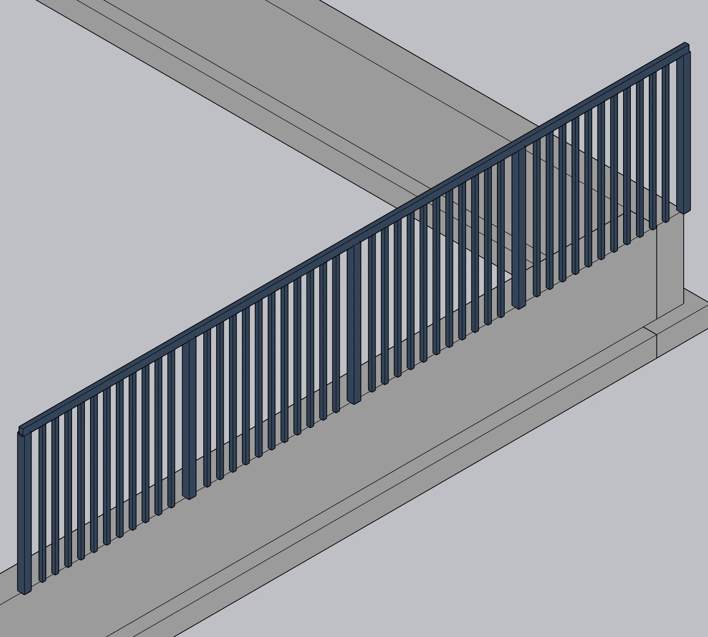
Railing and Handrail Modeling in SketchUp
Coordinate railing and handrail models in SketchUp with Lizark. Review stair and deck paths, posts, clearances and transitions in US residential design studies.
Follow the tutorial →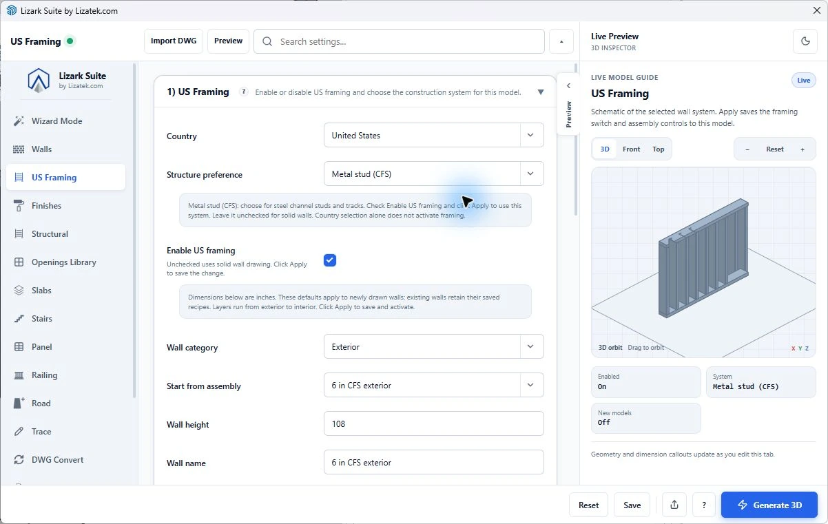
Cold-Formed Steel Framing in SketchUp
Explore cold-formed steel framing in SketchUp with Lizark. Choose the US steel profile and coordinate supported walls, floors and roofs in building studies.
Follow the tutorial →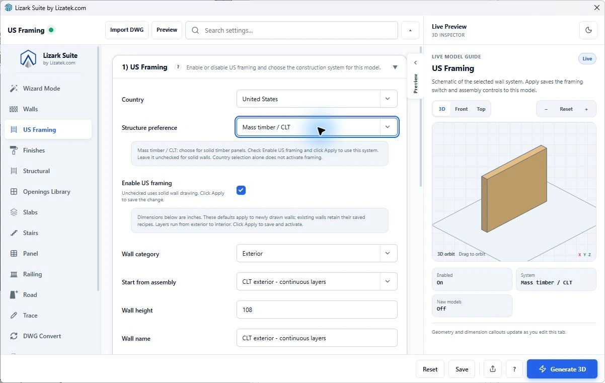
CLT and CMU Modeling in SketchUp with Lizark
Explore CLT and CMU modeling in SketchUp with Lizark. Select the US construction profile and coordinate panels, masonry walls and openings in building studies.
Follow the tutorial →Find the wall profile in Lizark Settings
Open Settings → US Framing. Choose your structure, review the starter assembly and dimensions, then scroll to Apply. The right panel is a schematic preview of the settings.
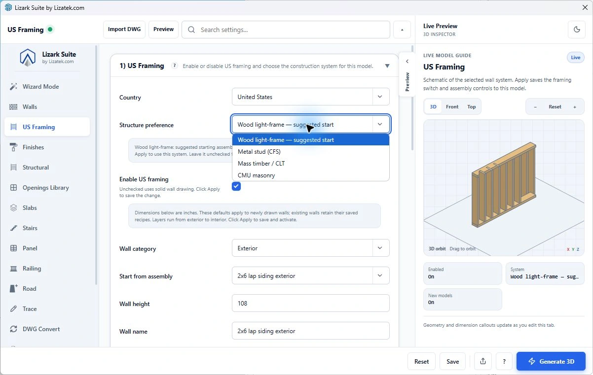
Choose wood, metal stud, CLT or CMU
- Choose the construction system in Structure preference.
- Enable US framing before applying the model profile.
- Review the starter assembly and wall height.
- Inspect the live schematic preview.
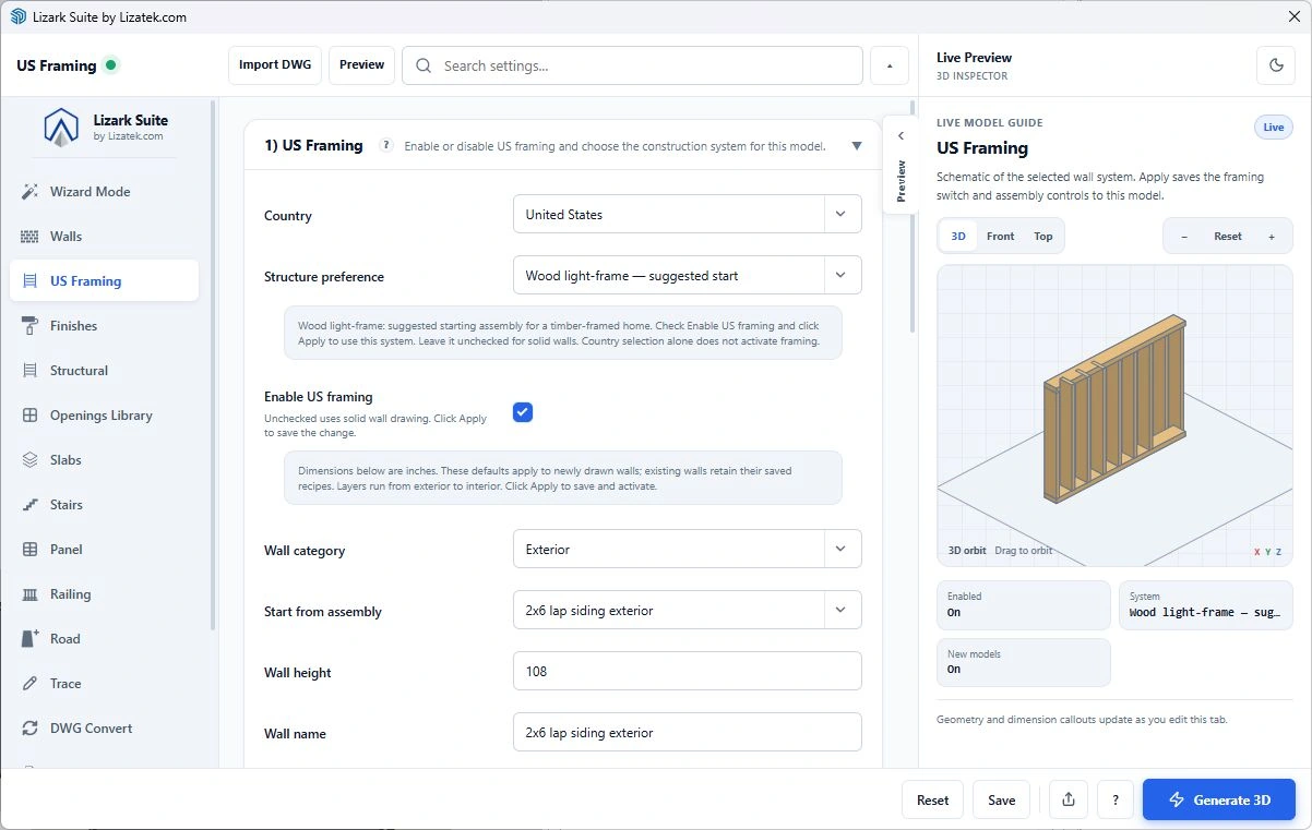
1. Choose and apply the US model profile
- Open Settings → US Framing. Choose United States.
- Select Wood light-frame, Metal stud (CFS), Mass timber / CLT or CMU masonry.
- Check US framing, review the wall controls, and click Apply US framing.
- Check Also use for new models before applying if you want these defaults in future models. Save the SKP to retain the current model profile.
The profile changes how supported new tools draw. It does not convert existing solid walls or existing timber geometry when you select another system.
2. Draw, trace or curve the wall path
Exit component editing and activate the relevant wall tool. Pick the start point and following points, use the tool’s length field for exact dimensions, and review the path before completing it. Draw Wall provides native placement; Trace Wall follows prepared references; Web Draw Wall provides the drafting canvas. The curved tool uses a center, radius and arc sweep.
Check wall side, reference alignment, height and corners before adding more geometry. Right-click the owned assembly to access the available wall, layer and opening commands. An ordinary solid wall remains on its existing tool path.
3. Adjust wall structure and finishes
| Control | Use it for |
|---|---|
| Height, alignment and display mode | Set the wall envelope and choose architectural, detailed or supported framing-only output. |
| Wood member sizes, spacing and plates | Control modeled stud depth/width, on-center spacing, top and bottom plates, and opening framing. |
| CFS depth, flange, lip and metal thickness | Define an open channel profile rather than a rectangular timber member. |
| Layer stack and panel thickness | Choose core, finish, sheathing and cavity dimensions; review side and layer order. |
| Color and texture mapping | Control layer materials, texture dimensions, rotation and offsets; keep custom texture files available. |
| Cladding courses, reveals and trims | Adjust finish layout and custom layer shapes within the tool’s supported limits. |
| Individual studs and connected updates | Edit owned framing members and apply compatible changes to connected assemblies. |
Controls depend on the selected system and wall type. CLT and CMU cores do not expose timber stud settings. Check an existing curved wall after replacing layers, especially around openings.
4. Place and finish openings
Use the supported door, window or ventilator workflow on an owned US wall. Set rough width, height, sill and header parameters; use finished opening commands for frame and casing dimensions. Shaped cuts and curved-wall finished components are included in the US workflow. Check repeated placements individually for correct host, side and sill elevation.
Moving or resizing an opening should update its host cut and framing. Test Undo and Redo on a copy of your project before a larger batch update.
5. Add floors, roofs and linked porches
Choose the tool matching the saved system. Wood uses joists and rafters; CFS uses channels with optional corrugated decking; CLT uses panels; CMU uses concrete slabs and roof panels. Set span, length, elevation, thickness or depth, spacing and roof pitch as applicable.
For roofs, review gable, shed, hip or authored geometry, then configure covering, fascia and soffits. Use wall-to-roof fitting on compatible owned walls and check the wall head at each roof plane. Polygon footprints and linked porch supports extend the US workflow; inspect angled and concave junctions in your own model.
Compare all four wall, floor and roof systems →6. Review, save and return to solid walls when needed
Inspect profile bends, open CFS sections, layer contact, finish reveals, opening cuts and support alignment. Rebuild an existing roof through its Lizark editing workflow to receive the latest seam cleanup. Save and reopen the SKP, then verify the model profile and edited geometry.
To resume solid walls, uncheck US framing in Settings and click Apply solid wall mode. Existing assemblies are preserved. Use model units consistently; accepted examples include 240in, feet/inches and metric lengths.
These are modeling presets, not load calculations, connection design or IRC/IBC certification. Explore the roadmap for future workflow additions.
Settings FAQ
Will enabling US framing change my existing solid walls?
No. In Lizark v1.0.24, choose United States, select a structure, check US framing, and click Apply. It routes supported new drawing to the selected system. Existing geometry is preserved.
Do I need to enable US framing every time?
Apply stores the profile in the current model. Save the SKP to retain it on reopen. Check Also use for new models before applying if you want the same defaults in future models. Uncheck US framing and Apply to return supported drawing to solid wall mode.
Are these engineered or code-approved assemblies?
No. Member dimensions, spacing, layers and roof pitch are modeling inputs. The presets do not calculate loads, connections, reinforcement or fire ratings and do not certify IRC or IBC compliance.