
US framing tutorial · Roof trusses
Roof Truss Modeling in SketchUp with Lizark
Roof truss modeling in SketchUp helps communicate the repeated roof system and the space it occupies. Lizark’s US workflow includes supported Fink and Howe truss study types. Use the model to coordinate the building form and bearing layout while keeping the truss supplier’s design information separate.
Follow along with numbered screenshots
Work in a separate practice model. These examples use Lizark 1.0.28 in SketchUp 2026. Read each action, enter the stated values, and check the result before continuing. Open any screenshot for a full-size view.
-
Step 1 · Choose the US wood profile
Open Lizark Settings → US Framing. Set Country to United States, choose Wood light-frame and check Enable US framing. For this exercise, use the 2x6 lap siding exterior assembly and a 108 in wall height. Scroll down and click Apply US framing before opening an assembly tool.
Screenshot 1 / 5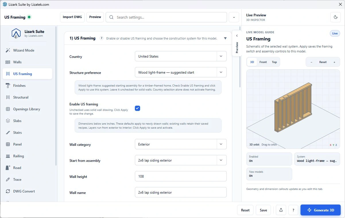
Fresh live Lizark configuration screen in SketchUp 2026. Open the image to read the controls at full size. View full size Checkpoint: The saved profile reports United States / Wood light-frame. A checked box or schematic alone does not mean the profile has been applied.
-
Step 2 · Open the US roof dimensions workflow
Open US Roof Framing. In Roof Builder, choose US roof system by dimensions. This opens the US framing builder where you can choose rafters or trusses. Use the US framing controls for this exercise rather than the separate Build Roof button.
Screenshot 2 / 5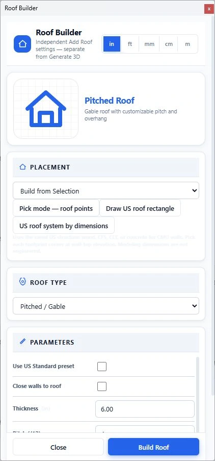
Fresh live Lizark configuration screen in SketchUp 2026. Open the image to read the controls at full size. View full size Checkpoint: The next dialog is titled Lizark US roof framing and offers Fink, Howe and rafter systems.
-
Step 3 · Choose the Fink truss system
In the US roof builder, select Dimensions and Fink. Review the schematic and distinguish it from the Howe and Rafters options. Keep the type unchanged while entering the footprint so the comparison uses the intended truss family.
Screenshot 3 / 5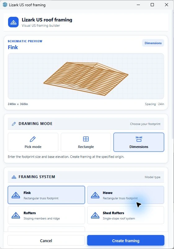
Fresh live Lizark configuration screen in SketchUp 2026. Open the image to read the controls at full size. View full size Checkpoint: Fink is highlighted and the preview contains internal truss webs.
-
Step 4 · Enter the footprint, elevation and pitch
Scroll to Footprint & Placement. Use a 240 in span and 360 in length. For a new standalone exercise, use Origin X and Y of 0 in; change Base elevation from the pictured 0 in to 108 in to match the wall-top study. Set Pitch (rise per 12) to 6 and Spacing to 24 in, then click Create framing. Keep Fink selected; the pictured footprint fields are shared with the rafter workflow.
Example inputs for step 4 Span / length 240in / 360in Origin X / Y 0in / 0in Base elevation 108in — change the pictured 0in Pitch / spacing 6 / 24in Screenshot 4 / 5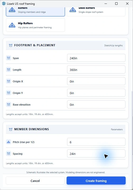
Fresh live Lizark configuration screen in SketchUp 2026. Open the image to read the controls at full size. View full size Checkpoint: The roof footprint is 20 × 30 ft. Pitch 6 means 6:12; it is not a six-degree slope.
-
Step 5 · Inspect one truss and then the full array
Use an end view to identify top chords, bottom chord and webs. Compare the complete array in plan and isometric views. Check the bearing locations and any service conflicts; obtain the project supplier’s truss information before preparing construction details.
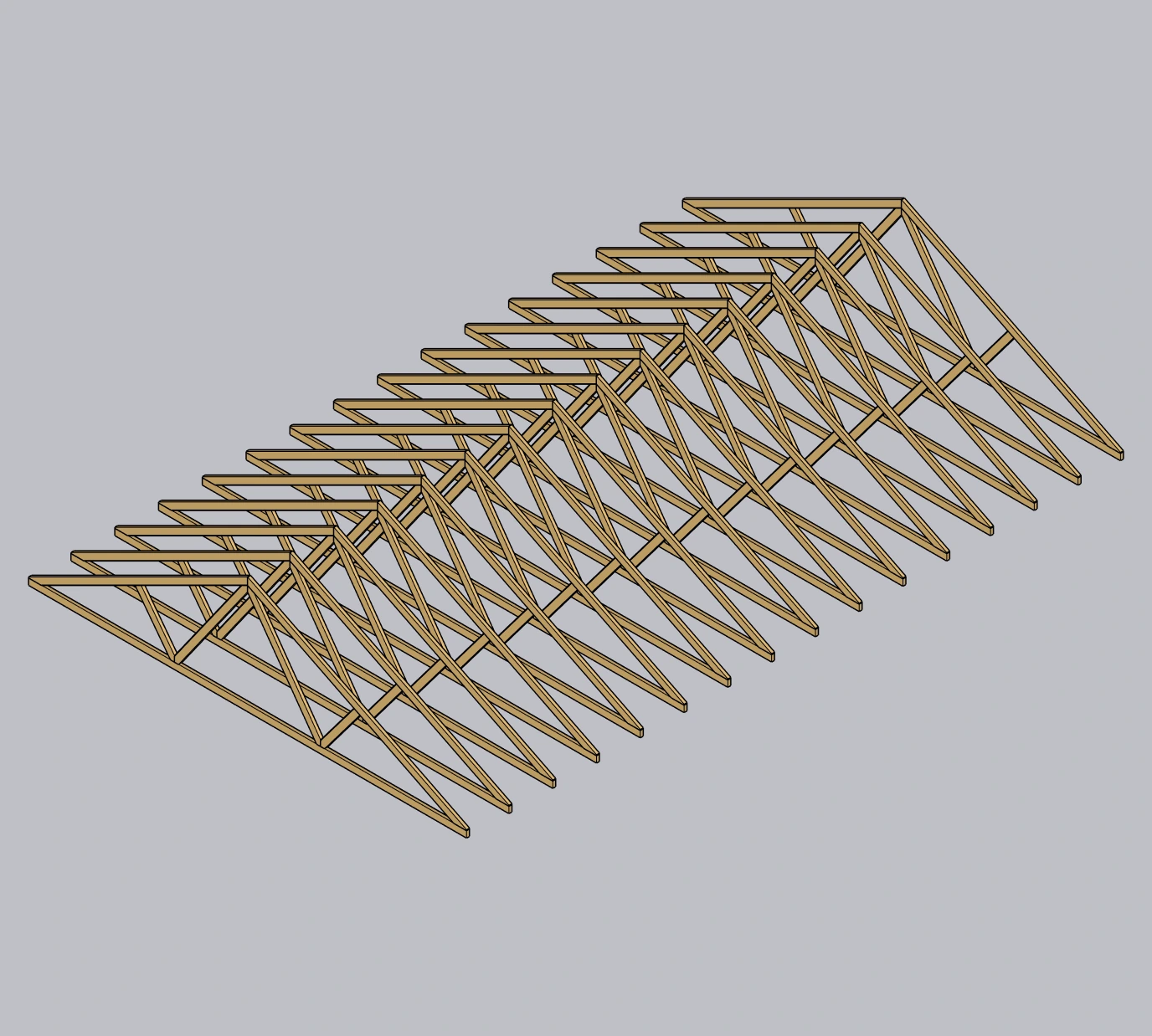
Screenshot 5 / 5Fresh live SketchUp result: the Fink array, shown without roof covering so its chord and web layout remains visible. View full size Checkpoint: Every repeated truss uses the intended layout. A clean model is not a supplier truss design.
Compare truss layouts for coordination
A Fink or Howe label describes a recognizable arrangement of chords and webs. It does not identify every engineered property of a manufactured truss. Choose the supported study type that best represents the proposed system, and label the model as a coordination study.
For an attic or service-space discussion, look at the web layout in section. A perspective of the roof exterior can hide the space occupied by the trusses. Compare alternatives in the same view and at the same base elevation.
Establish span, pitch and repetition
Use the US roof framing workflow to select the truss type and set the footprint, origin, base elevation, pitch and spacing. Review the generated run and its end conditions against the architectural plan.
Coordinate the bearing lines before treating the layout as settled. Interior supports, girder trusses, hips and valleys can require a different engineered arrangement from the simple repeated demonstration. Keep these conditions visible in the project notes.
Prepare a useful supplier conversation
Present the roof footprint, roof form, pitch, bearing layout and intended ceiling geometry together. Mark major openings and service zones. That gives a truss supplier a clearer design brief than an isolated screenshot.
Manufactured trusses should not be modified based on a visualization. Do not erase a web in SketchUp and imply the changed arrangement is acceptable. Request the supplier’s reviewed design and use it to update the coordination model.
Worked example: compare Fink and Howe layouts
Set up a rectangular roof study with a 20 ft span, 30 ft length and 6:12 pitch. Generate a supported Fink layout first and save the model or a separately named option. Use the same footprint and bearing elevation for a Howe comparison. This makes the web arrangement the visible change while the overall roof envelope remains easy to compare.
Inspect one truss in an end view before judging the full array. Identify the top chords, bottom chord and internal webs, then compare the array in plan. The fresh featured capture shows a Fink study without roof covering so those relationships remain visible. It is a modeling example, not a fabrication drawing or a supplier-designed truss package.
Add simple reference volumes for a stair opening, attic access or proposed service zone. Review whether the selected arrangement occupies the intended space. If a web conflicts with the design, document the conflict instead of removing it manually. A truss change needs coordination with the supplier and structural designer rather than a visual edit to make the rendering fit.
Keep bearing and repetition distinct
The interval between repeated trusses and the position of their bearing points answer different questions. Check both the repeated layout along the building and the support relationship across the span. At a gable end or a roof transition, do not assume the last repeated component describes every special condition.
Review changes in wall height, porch roofs and intersecting roof volumes before adding finishes. A regular array can still be offset from the intended wall line or placed at the wrong elevation. Save a section across representative bearings and a plan showing the full footprint. Where supplier information is available, compare the model with its designated truss types and layout references rather than a generic family name.
Prepare the supplier coordination questions
Include the architectural roof envelope, bearing references, openings and service-zone requests in the discussion. Identify any desired attic use and ceiling profile early. Keep the model assumptions visible and distinguish them from the supplier design. Connections, bracing, handling and installation requirements belong in the project documentation. The model helps locate questions and communicate space; it does not replace that information.
A practical Lizark workflow
- Choose the supported Fink or Howe study type.
- Set footprint, base elevation, pitch and spacing.
- Review the repetition against bearing lines.
- Create a section view showing ceiling and service space.
- Coordinate the study with the truss supplier’s design.
What to check in the model
| Review | What to verify |
|---|---|
| Study type | Fink or Howe identified clearly |
| Bearing | External and internal support locations |
| Space | Web layout, ceiling and services |
| Documentation | Supplier design required before fabrication |
Frequently asked questions
Does a truss model include engineered connector plates?
Do not assume it supplies fabrication or connection engineering. Obtain the truss supplier’s project-specific design.
Can I cut or remove a modeled web for a duct?
A model edit does not authorize a real truss modification. Coordinate proposed changes with the supplier or responsible designer.
Further reading
Product and industry references for the distinctions discussed in this guide: