
US framing tutorial · Foundations
Foundation Modeling in SketchUp with Lizark
Foundation modeling in SketchUp gives a residential design a visible base. Lizark’s supported US foundation workflow includes slab and stem-wall study types. Use these to coordinate the building footprint and floor elevations, while retaining the project’s soil, reinforcement and structural design information separately.
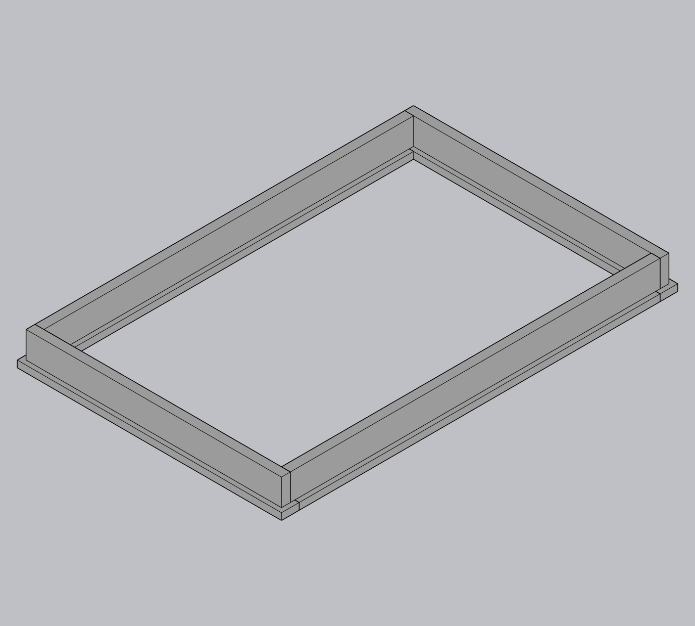
Follow along with numbered screenshots
Work in a separate practice model. These examples use Lizark 1.0.28 in SketchUp 2026. Read each action, enter the stated values, and check the result before continuing. Open any screenshot for a full-size view.
-
Step 1 · Choose the US wood profile
Open Lizark Settings → US Framing. Set Country to United States, choose Wood light-frame and check Enable US framing. For this exercise, use the 2x6 lap siding exterior assembly and a 108 in wall height. Scroll down and click Apply US framing before opening an assembly tool.
Screenshot 1 / 5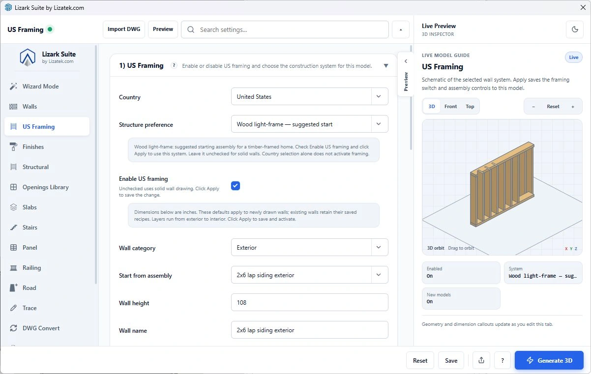
Fresh live Lizark configuration screen in SketchUp 2026. Open the image to read the controls at full size. View full size Checkpoint: The saved profile reports United States / Wood light-frame. A checked box or schematic alone does not mean the profile has been applied.
-
Step 2 · Select the stem-wall preset
Open US Foundations. In Foundation Presets, choose Stem wall and perimeter footing, then click OK. This opens the slab / foundation builder. The other presets represent different foundation conditions.
Screenshot 2 / 5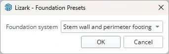
Fresh live Lizark configuration screen in SketchUp 2026. Open the image to read the controls at full size. View full size Checkpoint: The selected preset reads Stem wall and perimeter footing.
-
Step 3 · Choose Dimensions and Stem Wall
Select Dimensions in Drawing mode and keep Stem Wall highlighted. This uses the numeric footprint rather than asking for boundary clicks. Scroll down to the placement and member fields.
Screenshot 3 / 5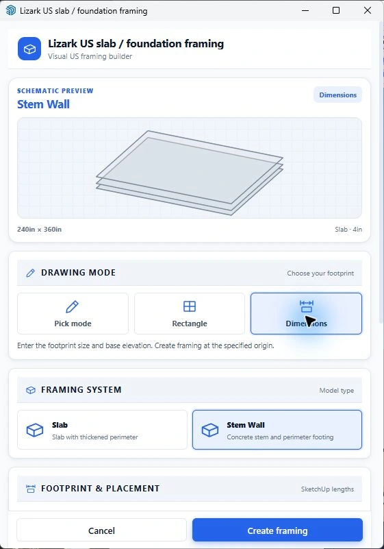
Fresh live Lizark configuration screen in SketchUp 2026. Open the image to read the controls at full size. View full size Checkpoint: Dimensions and Stem Wall are selected; the bottom button reads Create framing.
-
Step 4 · Enter the footprint and demonstration depths
Use the values below in a new standalone model and click Create framing. For a building project, replace the origin and base with the approved site and floor reference. The pictured depths are example inputs, not soil or reinforcement design.
Example inputs for step 4 Span / length 240in / 360in Origin X / Y / base 0in / 0in / 0in Slab thickness 4in Thickened edge depth / stem height 12in / 24in Screenshot 4 / 5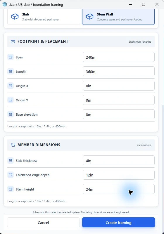
Fresh live Lizark configuration screen in SketchUp 2026. Open the image to read the controls at full size. View full size Checkpoint: The footprint measures 20 × 30 ft. Keep the slab, edge and stem dimensions distinct.
-
Step 5 · Inspect the perimeter and wall relationship
Review the perimeter in plan and an isometric view, then compare a section with the wall base and first floor. Look for a shifted footprint or inconsistent datum before coordinating the rest of the building.
Screenshot 5 / 5Fresh live SketchUp result: the stem-wall and perimeter-footing study. Structural and site details require separate project information. View full size Checkpoint: The stem-wall perimeter and footing are present and aligned with the intended building reference.
Choose the foundation condition
A slab-on-grade concept and a stem-wall concept describe different relationships between the floor and ground. Start with the intended project condition instead of choosing the shape that is easiest to draw.
Review the footprint against the walls and major support locations. For additions, show how new work relates to the existing building. The geometric relationship is useful for discussion even before the foundation design is fully developed.
Coordinate thicknesses and elevations
Review the supported slab thickness, thickened-edge depth and stem height inputs for the chosen type. Use explicit units and verify the resulting geometry in section. Define which elevation is the top of slab and which belongs to the framing above.
A visible thickened edge does not establish adequate footing width, frost protection, reinforcement or soil bearing. Record the demonstration inputs as model dimensions until the responsible designer specifies the real assembly.
Make the foundation useful for coordination
Place walls, floor systems and posts in the same reference system. Inspect perimeter offsets and transitions at garages, porches and entry doors. Save a section view through a representative wall-to-foundation condition.
Keep drainage, insulation, moisture control and penetrations in the project review. A clean foundation model communicates geometry; its simplicity should not hide the details needed for the actual site.
Worked example: coordinate a stem-wall perimeter
Start with a 20 ft by 30 ft building footprint and choose the supported stem-wall study. Record the origin, base elevation and the demonstration stem height before generating geometry. Inspect the result in plan and section. The featured capture shows the perimeter and footing relationship without pretending to specify reinforcement, soils or a complete construction detail.
Compare the foundation reference with the structural wall location above it. Finished siding and interior finishes may extend beyond the structural core, so the visible outside face is not always the bearing reference. Measure the offsets at a representative wall and at a corner. If a return or recess is part of the real plan, review that geometry before repeating a rectangular example across the project.
For an addition, include a clearly named representation of the existing foundation and floor level. Review new-to-existing transitions at doors, garages and porches. A continuous-looking floor surface can conceal a step or a different foundation condition underneath. Keep the existing dimensions marked as verified or assumed rather than mixing them with measured new work.
Use the model to locate site and interface questions
Show the approximate ground relationship with a separate reference surface where it helps explain the design. Then review drainage direction, wall exposure and the location of entries. Site grade, groundwater and frost considerations come from the project information and locally applicable requirements; a generic rectangle does not resolve them.
Coordinate penetrations and changes in floor level before developing a polished exterior view. Identify where plumbing, services or garage transitions interrupt the simple perimeter. A foundation study may remain intentionally simple, but the review notes should make those exceptions visible. Keep reinforcement and connection decisions associated with the responsible design documents.
Prepare foundation views for design coordination
Save a plan with the footprint references and a section through the wall, floor and foundation. Label top-of-slab, stem and framing datums explicitly. Include the origin of each dimension and identify unverified existing conditions. This gives the project team a consistent geometric basis for discussion while the site-specific footing, reinforcement and moisture-control details are developed.
A practical Lizark workflow
- Choose the supported slab or stem-wall study type.
- Set the footprint and origin from the architectural plan.
- Review the type-specific thickness and height inputs.
- Measure elevations and offsets in section.
- Coordinate wall, floor and post support locations.
What to check in the model
| Review | What to verify |
|---|---|
| Footprint | Wall edges and major support locations |
| Elevation | Top of slab, stem and framing references |
| Transitions | Garage, entry and porch levels |
| Design information | Soil, reinforcement and site-specific details |
Frequently asked questions
Does the foundation model include a soil-bearing design?
No. Obtain the site-specific foundation design and use it to coordinate the model.
Should the foundation footprint equal the finished wall outline?
Check the actual structural reference and assembly offsets. Do not assume the finished exterior surface controls the foundation edge.
Further reading
Product and industry references for the distinctions discussed in this guide: