
US framing tutorial · CLT & CMU
CLT and CMU Modeling in SketchUp with Lizark
CLT and CMU modeling in SketchUp requires different assembly assumptions from a stud-framed home. Lizark includes US mass timber / CLT and CMU construction profiles for supported modeling. Choose the intended system before generating geometry and review the continuous panel or masonry condition explicitly.
Follow along with numbered screenshots
Work in a separate practice model. These examples use Lizark 1.0.28 in SketchUp 2026. Read each action, enter the stated values, and check the result before continuing. Open any screenshot for a full-size view.
-
Step 1 · Identify the construction system
Open Settings → US Framing and choose United States. Open Structure preference. Use Mass timber / CLT for the panel option, or CMU masonry for the masonry option. Keep the comparison in separately named models or groups.
Screenshot 1 / 3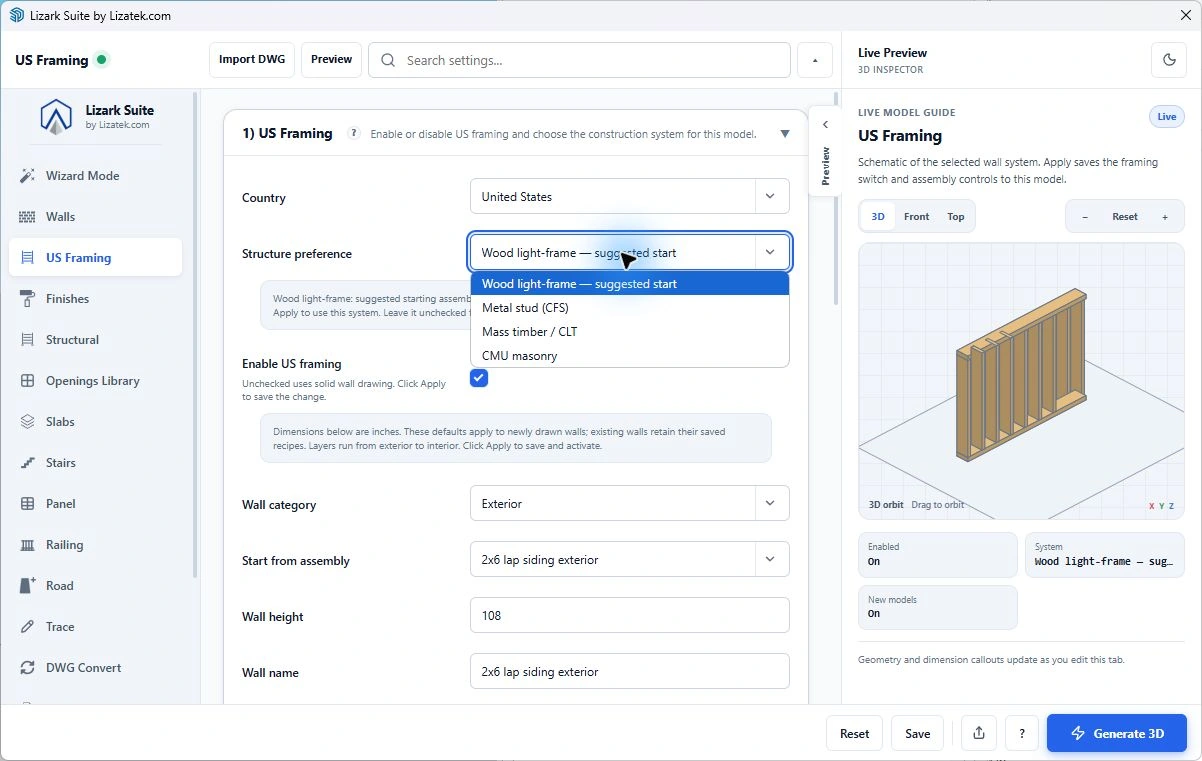
Fresh live Lizark configuration screen in SketchUp 2026. Open the image to read the controls at full size. View full size Checkpoint: The system menu contains distinct CLT and CMU choices; they are not stud-wall presets.
-
Step 2 · Review the CLT panel choice
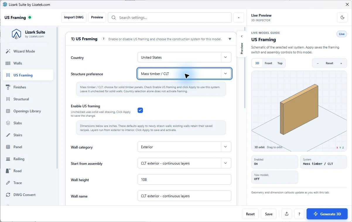
Choose Mass timber / CLT and check Enable US framing. Review the continuous-layer assembly and wall height, then inspect its schematic. Apply the reviewed profile before creating new supported geometry; confirm the saved-profile message. Keep panel thickness, joints and connection information tied to the selected product.
Screenshot 2 / 3Fresh live CLT Settings preview. This is a panel-system schematic, not a fabricated panel or a generated assembly. View full size Checkpoint: The CLT preview is a continuous timber panel. A schematic does not establish fabrication or connection details.
-
Step 3 · Review the separate CMU masonry option
For the alternative study, select CMU masonry. Review the 8 in nominal CMU exterior starter and the intended height; apply only the profile you intend to use. Keep masonry opening, lintel, reinforcement and grout requirements in the project documentation rather than inferring them from the smooth preview surface.
Screenshot 3 / 3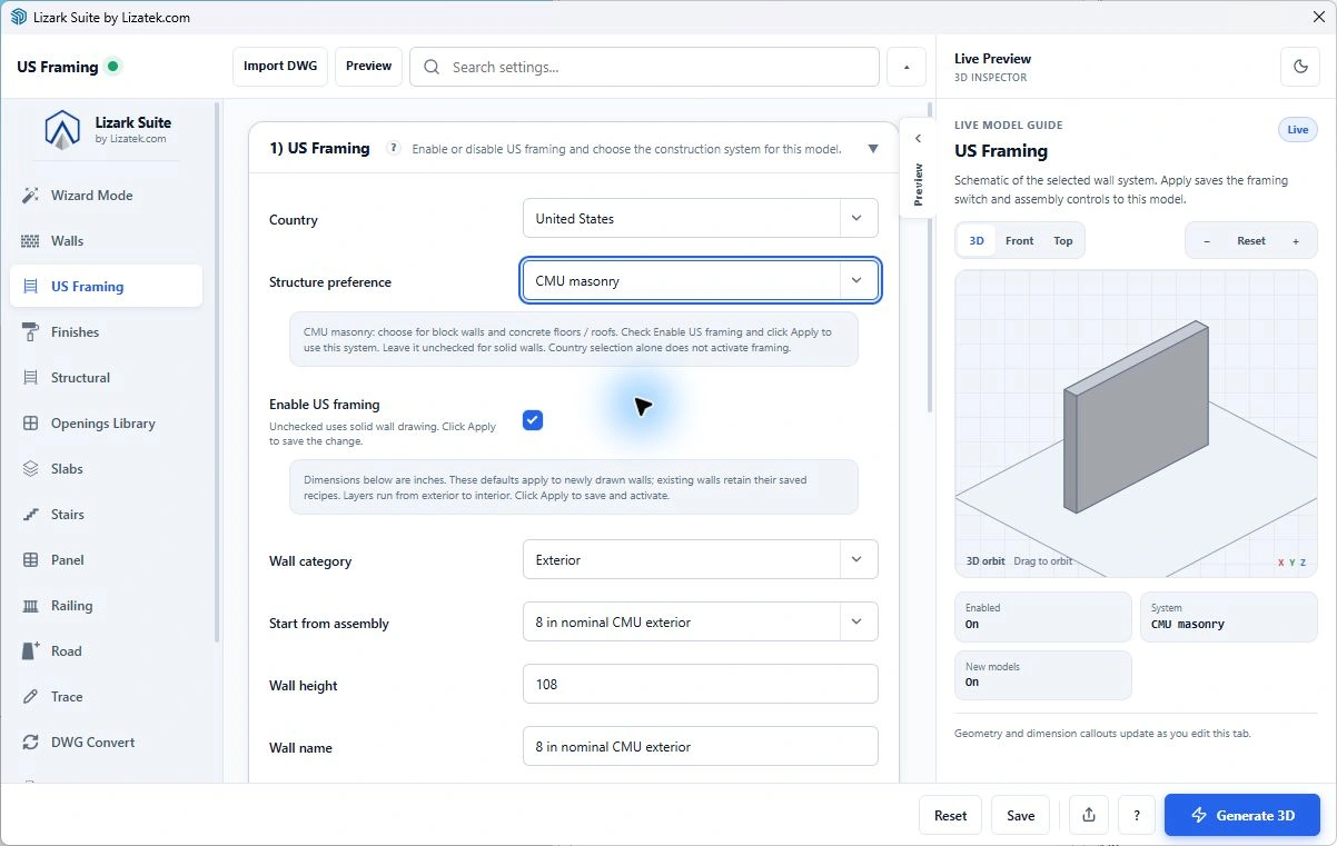
Fresh live CMU Settings preview captured October 12, 2026. It represents the construction choice, not individual blocks or reinforcement. View full size Checkpoint: The system label reads CMU masonry and the schematic differs from the timber panel. Previously created CLT geometry has not been converted.
Treat CLT as a panel system
Cross-laminated timber is a mass-timber panel system. It should not be presented as a repeated stud wall or decorative wood flooring. Review panel thickness, boundaries and the intended wall or floor role in the project model.
WoodWorks provides mass-timber technical resources that help frame the design conversation. Panel layout, fabrication, joints, connections and openings need coordination with the project team and supplier. A conceptual panel surface does not settle those details.
Treat CMU as a masonry assembly
Concrete masonry walls introduce block, reinforcement, grout, lintel and bond-beam questions. Use the selected masonry assembly information when describing the model. A solid-looking wall alone does not communicate all of those conditions.
The Concrete Masonry & Hardscapes Association publishes technical resources for masonry design and detailing. Consult the material relevant to the project rather than borrowing wood-framing assumptions for a masonry opening.
Compare systems without mixing their meaning
Apply the relevant US profile before creating each supported option. Profile changes do not convert existing assemblies. Keep CLT, CMU, wood and steel geometry clearly named when comparing space, depth and exterior proportions.
Review openings and floor-to-wall relationships for the selected system. Use sections to show assembly thickness and interfaces. For a client presentation, explain what the model demonstrates and identify the product and structural details that still need the responsible designer’s review.
Worked example: compare continuous systems on one footprint
Use a shared building footprint and floor datum to compare a CLT option with a CMU-based option. Apply the corresponding US profile before creating new geometry and save each option with its system name. Keep wall and roof assumptions explicit. A panel surface and a masonry wall may define similar exterior proportions while requiring different interfaces and opening details.
For the CLT option, inspect panel boundaries, thickness and the relationship to walls or beams. For the CMU option, inspect the masonry reference, opening locations and the concrete floor or roof relationship. A concrete surface generated under a CMU profile should be labeled as concrete; it is not a drawing of individual masonry units or reinforcement.
Use the same section location for both options. Compare clear interior space, assembly depth and transitions at the floor edge. Keep any proposed opening in the same architectural location, then identify the system-specific questions it creates. This gives the client a useful spatial comparison while preserving the distinction between the two construction methods.
Ask different questions for CLT and CMU openings
For CLT, coordinate panel cutting, joints and connection zones with the supplier and project team. A rectangular cut in a conceptual model does not settle fabrication tolerances or the connection detail at its edge. Identify the opening location and intended unit, then make supplier confirmation part of the review.
For CMU, review the opening with the masonry layout, lintel and reinforcement information. A smooth conceptual wall may be appropriate for an early design study, but it should not be presented as a fully detailed masonry assembly. Keep grout, reinforcement and bond-beam requirements in the design documentation rather than inferring them from a solid surface.
Keep the comparison useful as the design develops
Maintain separate model options and note which dimensions have been confirmed by the supplier or structural designer. Include a plan, representative section and exterior view for each system. Link the CLT discussion to the mass-timber references and the CMU discussion to the masonry references below. As details arrive, revise the relevant option and recheck openings and floor interfaces instead of changing both systems as if they were interchangeable.
A practical Lizark workflow
- Identify whether the option uses CLT panels or CMU masonry.
- Apply the corresponding US construction profile.
- Create new supported geometry with reviewed assembly inputs.
- Inspect openings, thickness and floor-to-wall interfaces.
- Coordinate supplier and structural details for the chosen system.
What to check in the model
| Review | What to verify |
|---|---|
| CLT | Panel role, thickness, joints and opening coordination |
| CMU | Masonry assembly, lintel and reinforcement information |
| Profiles | Correct system applied before creating new geometry |
| Presentation | Separate named options and representative sections |
Frequently asked questions
Is CLT the same as wood stud framing?
No. CLT is a mass-timber panel system with different fabrication and connection considerations.
Does a CMU wall model specify reinforcement and grout?
Do not assume it provides complete masonry engineering. Coordinate those requirements with the project’s design information.
Further reading
Product and industry references for the distinctions discussed in this guide: