
US framing tutorial · Floors
Floor Joist Framing in SketchUp with Lizark
Floor joist framing in SketchUp helps you show floor depth and member direction before detailing a home. Lizark’s US floor workflow offers supported joist, I-joist and floor-truss models. Establish the footprint and base elevation, then review the system alongside walls, stairs and the subfloor.
Follow along with numbered screenshots
Work in a separate practice model. These examples use Lizark 1.0.28 in SketchUp 2026. Read each action, enter the stated values, and check the result before continuing. Open any screenshot for a full-size view.
-
Step 1 · Choose the US wood profile
Open Lizark Settings → US Framing. Set Country to United States, choose Wood light-frame and check Enable US framing. For this exercise, use the 2x6 lap siding exterior assembly and a 108 in wall height. Scroll down and click Apply US framing before opening an assembly tool.
Screenshot 1 / 4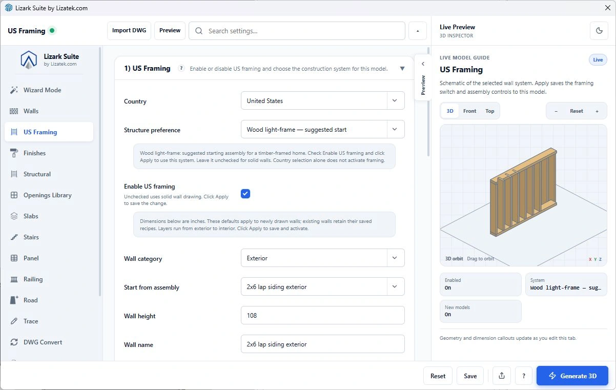
Fresh live Lizark configuration screen in SketchUp 2026. Open the image to read the controls at full size. View full size Checkpoint: The saved profile reports United States / Wood light-frame. A checked box or schematic alone does not mean the profile has been applied.
-
Step 2 · Choose Dimensions and Joists
Open US Floors / Decks. Select Dimensions under Drawing mode, then select Joists under Framing system. Dimensions mode creates the footprint from numeric inputs; Pick mode instead asks you to mark boundary points in the model.
Screenshot 2 / 4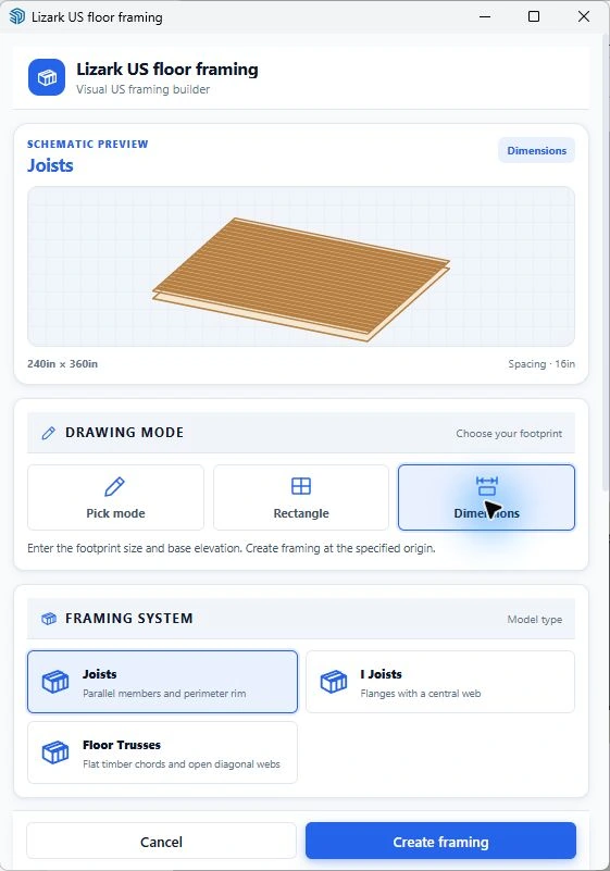
Fresh live Lizark configuration screen in SketchUp 2026. Open the image to read the controls at full size. View full size Checkpoint: Dimensions and Joists are highlighted, and the bottom button reads Create framing.
-
Step 3 · Enter floor dimensions and create the study
Scroll to Footprint & Placement and Member dimensions. In a new exercise model, enter the values below, then click Create framing. Use explicit units. The chosen origin is for a standalone exercise; place the assembly at your project’s bearing reference when coordinating a building.
Example inputs for step 3 Span / length 240in / 360in Origin X / Y / base 0in / 0in / 0in Member depth / spacing 9.25in / 16in Subfloor thickness 0.75in Screenshot 3 / 4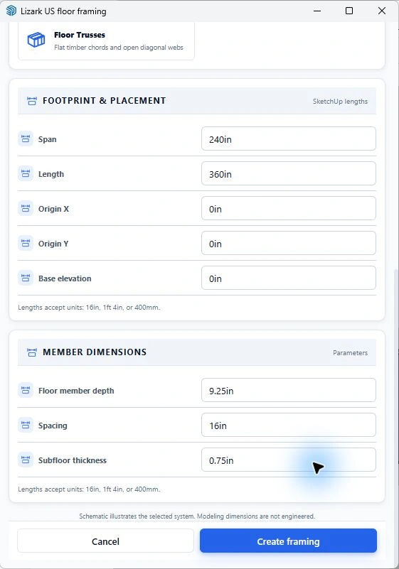
Fresh live Lizark configuration screen in SketchUp 2026. Open the image to read the controls at full size. View full size Checkpoint: The footprint measures 20 × 30 ft and the member depth plus subfloor gives a 10 in study buildup.
-
Step 4 · Review the floor against its supports
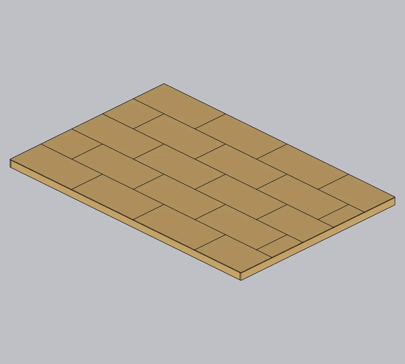
Use Zoom Selection on the generated assembly and review it from above and below. The screenshot shows the subfloor surface. Check member direction against bearing lines, then compare a section with the intended finished floor and stair landing elevations.
Screenshot 4 / 4Fresh live SketchUp result: the US floor study with its subfloor visible. Inspect below this surface to review the members. View full size Checkpoint: Confirm the support concept and any stair or service openings before treating the repeated layout as a framing plan.
Choose the system before the member depth
Solid joists, I-joists and floor trusses have different geometry and detailing needs. APA describes I-joists as engineered products; the selected manufacturer’s literature matters when you move beyond a visual study. A model depth or spacing is an input, not a verified span capacity.
For a concept model, create separate options rather than disguising one system as another. Use clear assembly names and compare total floor depth at the same elevation. This makes the effect on story height and stair coordination easier to explain.
Set footprint, direction and elevation
Use US Floors / Decks and choose the supported model type. Review span, length, origin, base elevation, member depth, spacing and subfloor thickness before generating geometry. Explicit units reduce ambiguity when the architectural plan uses feet and the framing inputs use inches.
Check which dimension controls the member span and which controls the repeated run. Rotate or position the supported assembly as required, then inspect its edges against the bearing layout. An evenly spaced floor model still needs a project-specific support and connection design.
Coordinate the floor with stairs and services
Review the subfloor surface with the finished floor reference. A small thickness mismatch can affect the top stair landing and door threshold in a tightly coordinated model. Keep the structural and finished elevations named in your notes.
Reserve space for the stair opening and major service routes. Do not interpret an open area in a visualization as permission to cut an I-joist flange or alter a manufactured truss. Product-specific hole, notch and modification rules belong in the construction review.
Worked example: a 20-by-30-foot floor study
Begin with a 20 ft by 30 ft footprint, a 9.25 in member-depth input and a 0.75 in subfloor input. In this exercise, those two layers produce a 10 in modeled buildup before other finishes are considered. Record whether the base elevation refers to the underside of the joists or another datum, then measure the top surface in the generated model. These are demonstration inputs rather than a span recommendation.
Set the joist direction deliberately and compare it with the proposed bearing lines. The long dimension of the room is not automatically the joist span. Sketch a stair opening and identify the floor members it would interrupt. Resolve its location before presenting the repeated joist layout as a finished framing plan.
Compare the ordinary joist option with an I-joist or floor-truss study using the same plan boundary and floor reference. Review the resulting depth and interfaces, not just the appearance of the webs. A changed floor depth affects stairs, door thresholds, ceiling heights and the relationship to an adjoining existing floor.
Coordinate service routes and floor openings
A large duct or plumbing route deserves a place in the coordination model. Show its intended zone with a clearly named reference volume and inspect it against the joists, beams and stair opening. An open-web appearance does not mean every route fits or that an arbitrary member can be removed. Engineered products require their own hole and installation guidance.
APA explains that allowed holes depend on the product and their location, and that notching requires particular care. Use the selected manufacturer documentation when coordinating penetrations. Do not erase a joist web in SketchUp and treat the resulting space as an approved field modification. Record the issue and obtain a detail for the actual floor system.
Save floor views that explain the support concept
Use a plan to show member direction and support lines, a section to show floor buildup, and a perspective to explain the assembly to the homeowner. Mark unresolved openings and service conflicts. Include the product family and depth assumptions in the notes. A model quantity check can count repeated geometry, but ordering also depends on actual member lengths, product specifications, connections and allowances that the visual study does not settle.
A practical Lizark workflow
- Apply the US construction profile for the intended floor system.
- Choose joists, I-joists or floor trusses in the supported workflow.
- Set footprint, origin, elevation, depth and spacing.
- Review subfloor thickness and member direction.
- Compare walls, stair landings and the support layout in section.
What to check in the model
| Review | What to verify |
|---|---|
| Footprint | Span direction and repeated length |
| Elevation | Structural base and finished floor reference |
| Floor depth | Members, subfloor and finish buildup |
| Coordination | Bearing lines, stairs and major services |
Frequently asked questions
Can Lizark model I-joists and floor trusses?
The US floor workflow includes supported I-joist and floor-truss model types. Select the intended type before generating the floor.
Does member spacing establish a safe span?
No. Span depends on the selected product, loading, support and design criteria. Use the relevant engineering information.
Further reading
Product and industry references for the distinctions discussed in this guide: