
US framing tutorial · Railings
Railing and Handrail Modeling in SketchUp
Railing and handrail modeling in SketchUp helps clarify the edges of decks, balconies and stairs. Lizark’s railing workflow can support these presentation studies. Establish the finished walking surfaces and paths before selecting the railing appearance, then check the transitions and clearances in the building model.
Follow along with numbered screenshots
Work in a separate practice model. These examples use Lizark 1.0.28 in SketchUp 2026. Read each action, enter the stated values, and check the result before continuing. Open any screenshot for a full-size view.
-
Step 1 · Choose Metal Baluster
Open Add Railing to display Lizark Rail. Select Metal Baluster and set the units to in. Review the live preview before configuring height, path direction, posts and infill. The current preview is schematic, not a placed railing.
Screenshot 1 / 3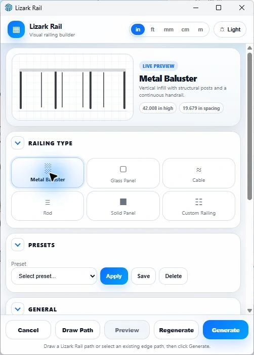
Fresh live Lizark configuration screen in SketchUp 2026. Open the image to read the controls at full size. View full size Checkpoint: Metal Baluster is selected. The bottom of the dialog provides Draw Path and Generate controls.
-
Step 2 · Set dimensions and draw a simple path
In General, change the pictured height to 42 in, set Path Offset to 0 and choose Center for Direction instead of the pictured Right. Keep Stair Mode off for this straight study. In Posts and Balusters, review the example values below. Click Draw Path, pick the start and end on a level reference, then press Enter to finish. If the path remains selected without an assembly, use Generate.
Example inputs for step 2 Height / offset / direction 42in / 0in / Center Post width / depth / spacing 2in / 2in / 48in Baluster width / spacing 1in / 4in Stair mode Off Screenshot 2 / 3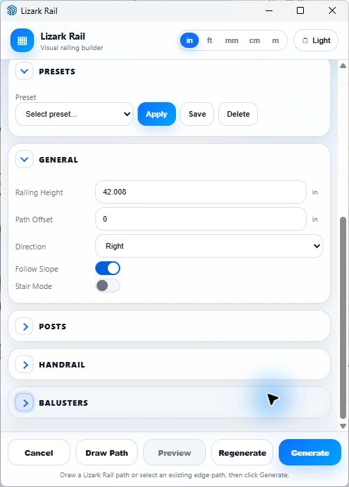
Fresh live Lizark configuration screen in SketchUp 2026. Open the image to read the controls at full size. View full size Checkpoint: The path follows the intended edge. The values illustrate geometry and do not establish guard or handrail compliance.
-
Step 3 · Inspect the entire generated run
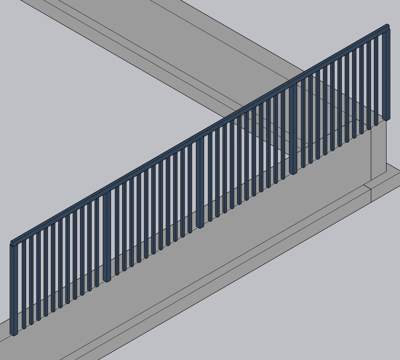
Return to Select and inspect the railing along its full path. Compare end posts, repeated infill and handrail alignment with the support edge. Review disconnected runs separately. Restore the finished walking surface when checking door and landing clearances.
Screenshot 3 / 3Fresh live SketchUp result: a standalone metal baluster run beside a reference edge, not a finished deck connection assembly. View full size Checkpoint: Every intended run exists and its posts align with the support concept; connection design remains a project detail.
Separate the guard from the handrail
A guard protects an open edge; a handrail provides a graspable support along circulation. A single assembly may include both, but they serve different purposes. Identify which condition each modeled element represents in your notes.
Start from the actual stair, deck or landing geometry. A railing placed before floor elevations are settled may look correct at one end while floating or colliding at the other. Review the entire path in elevation and section.
Review paths, posts and transitions
Use supported railing inputs and paths rather than relying on a decorative component stretched to fit. Inspect corners, landings and slope changes. Each disconnected run needs deliberate review so the presentation does not silently omit an edge.
Post positions should be coordinated with the underlying structure. Repeated visual spacing is not a connection design. On a deck, compare posts with the rim and support concept; on a stair, inspect the relationship to treads and landings.
Check clearances before rendering
Look for collisions at door swings, tight stair turns and landing entrances. Show the usable walking area in plan. A close camera angle can conceal a transition problem that becomes obvious in a simple elevation.
Confirm the project’s guard, handrail and opening requirements with the locally applicable design criteria. Lizark’s model is a coordination aid; appearance alone does not establish strength, graspability or compliance.
Worked example: a deck edge with a stair opening
Begin with the platform surface and leave the stair access visible. Define one railing run on each side of the opening rather than stretching a continuous decorative component across it. Check the path start and end against the finished surface. This exercise is about path coordination; the actual height, opening limits and connection details come from the project requirements.
At each corner, inspect the relationship between the final post of one run and the first post of the next. Look for duplicated posts, a visible gap or a rail extending into circulation. On the stair, review the slope-to-landing transition in elevation. A clear plan can still hide a railing that is floating above the steps or terminating short of the intended location.
Compare the proposed post positions with the underlying rim, beam or landing structure. Keep the posts visible in a structural review view even if planting or furniture will hide them in the final presentation. A repeated spacing input organizes geometry, but it does not establish anchorage or the ability of the support to resist the required loads.
Separate infill appearance from usable clearance
Pickets, glass and cable create different visual effects and different detailing questions. Before selecting the appearance, check the walking path, door swings and landing entrances. Make the usable space clear in plan so a thin-looking rail is not accepted merely because it disappears in the rendering.
Review each disconnected path after changes to stairs or floor elevations. A railing may remain at its original height or position when the supporting geometry changes. Inspect its full length and both ends; do not rely on the first post as proof that the run is coordinated. Keep guard and graspable handrail purposes explicit, especially where one assembly is expected to serve both.
What a railing review should contain
Provide a plan of the paths, elevations through transitions and a close view of representative posts. Record the intended system and the required guard or handrail function. Include unresolved ends, corners and connection questions in the notes. The model can communicate appearance and placement, while strength, graspability and locally applicable dimensions remain tied to the selected product and project design.
A practical Lizark workflow
- Set the finished deck, stair and landing elevations.
- Define each supported railing path and its intended purpose.
- Choose the assembly and review its inputs.
- Inspect posts, corners and slope-to-landing transitions.
- Check clear circulation and document the required design review.
What to check in the model
| Review | What to verify |
|---|---|
| Purpose | Guard, handrail or a combined assembly |
| Continuity | Every run and transition inspected |
| Posts | Relationship to supporting structure |
| Clearance | Doors, landings and walking paths |
Frequently asked questions
Are a guard and a handrail the same thing?
They serve different purposes. Identify and review both requirements for the intended condition.
Can a railing rendering prove compliance?
No. Review dimensions, opening limits, strength, graspability and the applicable project requirements separately.
Further reading
Product and industry references for the distinctions discussed in this guide: