
US framing tutorial · Cold-formed steel
Cold-Formed Steel Framing in SketchUp
Cold-formed steel framing in SketchUp needs a steel-specific model rather than wood studs recolored gray. Lizark includes a US cold-formed steel construction profile for supported workflows. Apply it before creating new assemblies and review the resulting member shapes and system inputs.
Follow along with numbered screenshots
Work in a separate practice model. These examples use Lizark 1.0.28 in SketchUp 2026. Read each action, enter the stated values, and check the result before continuing. Open any screenshot for a full-size view.
-
Step 1 · Choose the steel construction profile
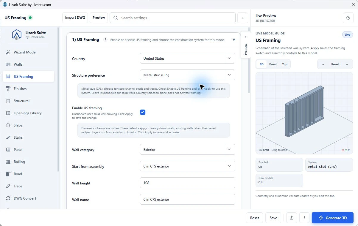
Open Settings → US Framing, choose United States and open Structure preference. Select Metal stud (CFS). This menu also contains wood, CLT and CMU; changing a choice here does not convert existing geometry.
Screenshot 1 / 2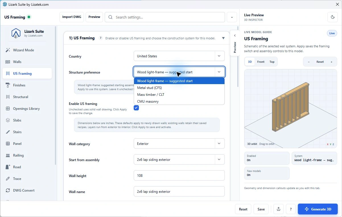
Fresh live Lizark configuration screen in SketchUp 2026. Open the image to read the controls at full size. View full size Checkpoint: The selected system is Metal stud (CFS), not Wood light-frame.
-
Step 2 · Review the CFS assembly before applying it
Check Enable US framing and review the steel starter assembly, wall category, height and channel dimensions against the intended product. The pictured 6 in CFS exterior and 108 in height identify a study choice. Scroll to Apply US framing and continue only after the saved-profile confirmation appears. If validation reports an unsupported dimension, correct the assembly inputs before generating anything.
Screenshot 2 / 2Fresh live Settings schematic: the CFS construction choice. This illustrated sequence covers profile setup, not a generated steel building. View full size Checkpoint: The preview shows a steel wall schematic. It is not proof of generated steel geometry or a saved profile.
Use steel-specific product information
Cold-formed steel members have designation, thickness and section information that differs from nominal lumber terminology. SFIA’s technical resources provide industry background and product-reference material for steel framing discussions.
Choose the intended member information from the project specification. A visual model should communicate the selected system clearly without inventing material strength or substituting a generic thickness for a specified product.
Apply the profile before creating geometry
Select United States and the cold-formed steel system in Lizark Settings, enable US framing and apply the profile. Review the supported assemblies and inputs before drawing walls or generating floors and roofs.
Changing Settings prepares subsequent supported geometry; it does not automatically convert the wood assemblies already in the file. Keep the steel option in a clearly named model or assembly group when comparing alternatives.
Coordinate openings and service zones
Review the steel wall depth and opening relationships with the architectural door and window units. Inspect framing around the opening, then compare the finished wall view. The finish buildup can differ from a wood option even when the room layout stays the same.
Connections, bracing, service holes and corrosion protection need project-specific decisions. Use the model to locate questions for the responsible designer, and keep engineering information attached to the selected system rather than inferred from its appearance.
Worked example: compare a steel option with a wood study
Save the wood option before changing the construction profile. Apply the US cold-formed steel profile, then create new supported geometry with the same architectural footprint and a recorded elevation. Keep the two options separately named. Changing the profile does not convert the wood assembly, so the comparison must identify which geometry belongs to each system.
Inspect a representative generated member from the end when reviewing a steel model. A C-section or track has a different shape from a solid timber rectangle. Review the entered depth, flange, lip and thickness information against the intended product. The fresh image in this guide shows the live Settings wall schematic for the CFS choice; it does not show a generated steel roof or establish its member specification.
Compare wall depth, floor buildup and roof interfaces before choosing the preferred appearance. Similar room dimensions can hide different finish layers or bearing relationships. Save a section through each option using the same cut and datum so the differences are visible and can be checked.
Read product designations before entering dimensions
Use the specified steel product information as the input source. Member designation, design thickness, coating and material properties are distinct pieces of information. Do not treat an informal gauge label as a complete product specification, and do not infer capacity from the depth of the modeled section.
SFIA publishes technical product resources for cold-formed steel framing. Use the relevant documentation with the project specification to identify the intended sections. The SketchUp model can make section geometry and placement readable, but it does not calculate member capacity, bracing or connection performance. Keep those references attached to the steel option so the geometry is interpreted correctly.
Coordinate details that a repeated array omits
Review opening supports, tracks, bridging, service routes and interfaces with other materials as separate questions. A regular array is useful for the first spatial study; it is not a complete shop drawing. Mark unresolved connections and service conflicts, then compare them with the design information. Finish the review with a system-specific section and a clearly labeled perspective of the steel option.
A practical Lizark workflow
- Select and apply the US cold-formed steel profile.
- Review the specified member and assembly information.
- Create new supported assemblies for the steel option.
- Coordinate openings, floor depths and roof relationships.
- Compare the model with project-specific steel design information.
What to check in the model
| Review | What to verify |
|---|---|
| Member identity | Section designation and specified thickness |
| Assemblies | Steel profile applied before generation |
| Comparison | Existing wood geometry kept distinct |
| Details | Connections, bracing and services reviewed |
Frequently asked questions
Does changing the profile convert existing wood walls?
No. Apply the profile for new supported geometry and keep existing systems clearly identified.
Can I use lumber labels for steel member sizing?
Use the steel product designation and specification. Steel member information differs from nominal lumber labels.
Further reading
Product and industry references for the distinctions discussed in this guide: