
US framing tutorial · Walls
Wood Wall Framing in SketchUp with Lizark
Wood wall framing in SketchUp helps US residential designers show the studs, plates and openings behind a finished wall. Lizark uses a saved US construction profile to create supported assemblies as native SketchUp geometry, so you can review structure alongside the architectural design.
Follow along with numbered screenshots
Work in a separate practice model. These examples use Lizark 1.0.28 in SketchUp 2026. Read each action, enter the stated values, and check the result before continuing. Open any screenshot for a full-size view.
-
Step 1 · Choose the US wood profile
Open Lizark Settings → US Framing. Set Country to United States, choose Wood light-frame and check Enable US framing. For this exercise, use the 2x6 lap siding exterior assembly and a 108 in wall height. Scroll down and click Apply US framing before opening an assembly tool.
Screenshot 1 / 3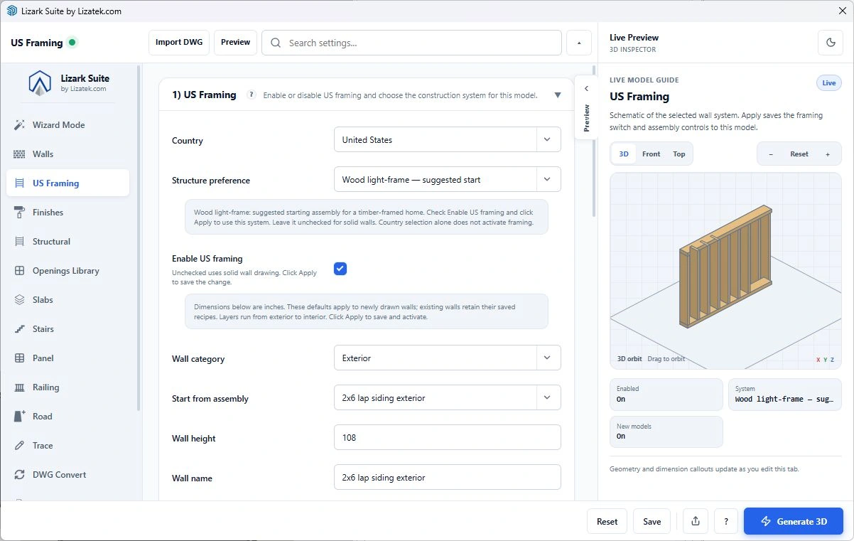
Fresh live Lizark configuration screen in SketchUp 2026. Open the image to read the controls at full size. View full size Checkpoint: The saved profile reports United States / Wood light-frame. A checked box or schematic alone does not mean the profile has been applied.
-
Step 2 · Review the layers and apply the assembly
Scroll to the bottom of US Framing. Review the cladding, sheathing, structural cavity and interior finish layers, then click Apply US framing. Also use for new models is optional: leave it unchecked if this exercise should affect only the current model. Close Settings after the saved-profile message appears.
Screenshot 2 / 3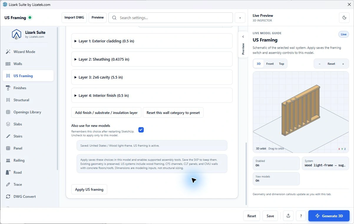
Fresh live Lizark configuration screen in SketchUp 2026. Open the image to read the controls at full size. View full size Checkpoint: The complete assembly depth includes the finishes. Confirm the saved-profile message before drawing the wall.
-
Step 3 · Draw the wall and inspect its framing
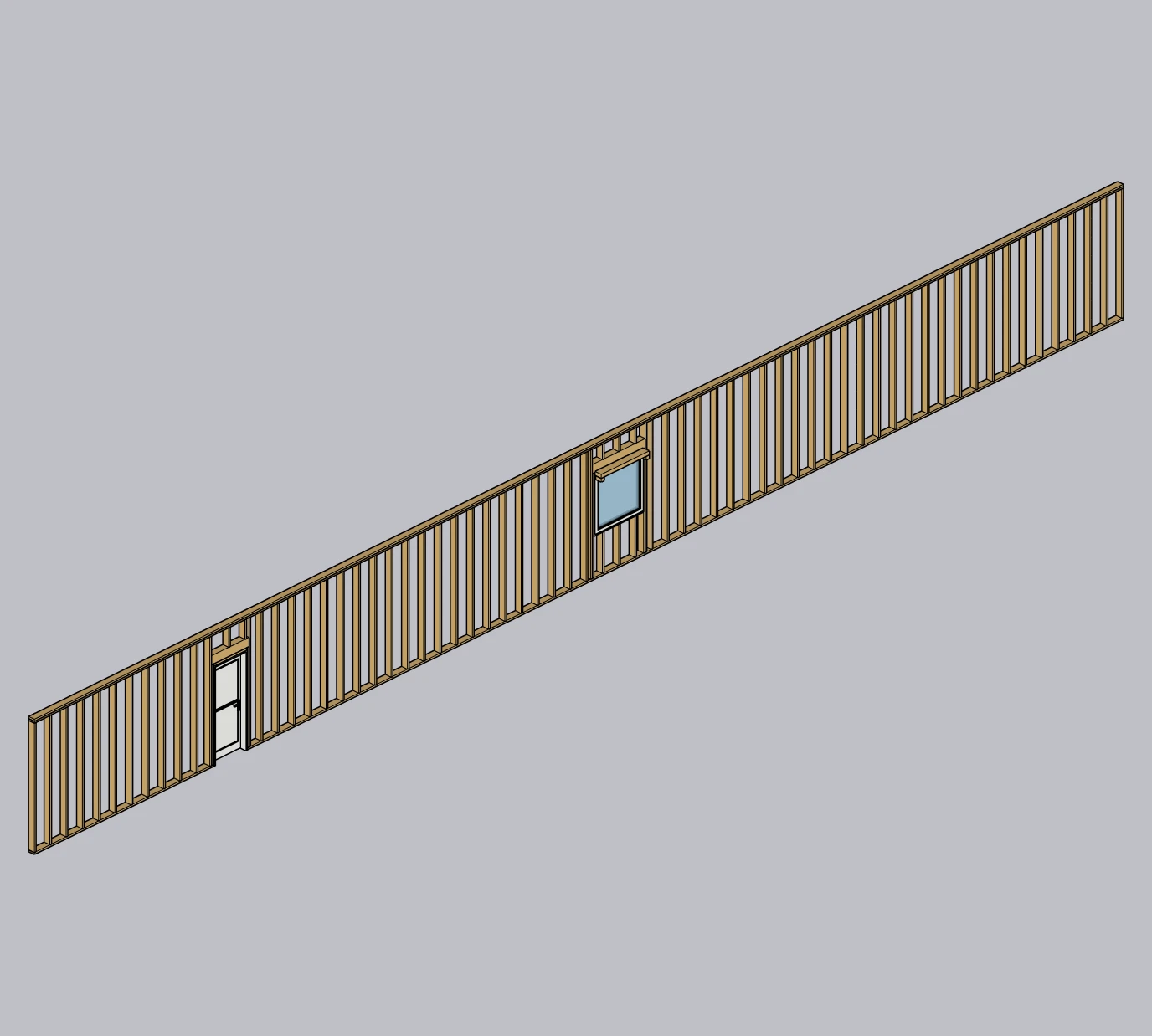
Activate Draw Wall, establish the first point on your intended floor plane and define a 20 ft wall along the chosen reference. Keep finishes visible when adding a door or window. After placement, select the assembly and use Lizark US view → Show structural core. The door and window guides below show their configuration steps.
Screenshot 3 / 3Fresh live SketchUp result: wood studs and plates around a Shaker door and fixed window. Openings are the next exercise, not an automatic part of drawing a blank wall. View full size Checkpoint: Measure wall length, base and height. Compare the structural view with the finished view; the screenshot shows the wall after its openings have been added.
Start with the assembly, then draw the wall
In Lizark Settings, choose United States and Wood light-frame, enable US framing, and apply the profile before drawing new walls. Review the assembly recipe as well as the member dimensions. A wall includes more than its structural core: sheathing, exterior finishes and interior layers affect its total depth.
For an addition or garage concept, establish the wall path and story elevation first. Check which reference line controls placement so the framing and finishes land on the intended side of your plan. Use explicit units in supported length fields, such as 20ft or 240in, and measure the resulting model.
Read the framing view
Select a supported assembly and use Lizark US view → Show structural core to inspect the framing. Restore normal layers when you need the finished wall face again. These views let a homeowner see the difference between the structural wall and the finished room boundary.
Look at plate continuity, wall ends, corners and the spaces reserved for openings. Regular stud spacing is one input; the framing around a door or window also depends on the opening and its location. Review both in the model instead of assuming a repeated array covers every condition.
Keep edits connected to the assembly
Use supported Lizark wall controls when changing wall height, ends or openings. Save a separate model before experimenting with assembly changes. Manually erasing individual faces can leave an attractive picture that no longer agrees with the assembly inputs.
Changing the construction profile sets up new geometry; it does not convert every existing wall. For mixed systems, name the assemblies and organize views so a wood wall is not mistaken for a steel or masonry wall.
Worked example: coordinate a garage wall before adding openings
For a garage addition study, begin with a 20 ft wall path and a 9 ft wall height. Record the baseline elevation and the reference used for the path. These numbers establish a repeatable modeling exercise; the wall assembly and structural dimensions still come from the project specification. Create the wall without openings first and measure its ends, height and complete depth.
Now add a pedestrian door near one end and a window farther along the same wall. Restore the finished face for placement, then switch to the structural view. Compare the opening positions with the measured ends instead of judging them from perspective alone. A dimension from the wall end to an opening jamb is more useful for coordination than the distance to decorative casing.
Save one view looking along the wall and another looking at its broad side. The first exposes offsets and finish buildup; the second makes the opening arrangement readable. If the wall will connect to a return, study that corner before repeating the assembly around the rest of the addition. This keeps an incorrect placement reference from spreading through the model.
Troubleshoot wall depth and opening placement
If a wall appears thicker than expected, inspect the complete assembly rather than immediately changing the stud size. Interior finish, sheathing, insulation layers and siding can contribute to the visible depth. Compare the structural-core view with the finished view, then measure both. Keep a note of which dimension belongs to the framing and which belongs to the overall envelope.
If an opening will not place on the intended wall, return to Select, exit group editing and restore normal assembly layers. Confirm that you are picking the broad host face rather than a narrow wall end, a roof face or a decorative component. Place a single opening and inspect it before repeating the command. When an existing model uses a different construction profile, create a separate test assembly under the current profile instead of assuming it was converted.
What to save for a wall review
Give the assembly a recognizable project label and save the SKP with the profile choice. Include the wall reference, base elevation, opening locations and finish depth in the review notes. A homeowner presentation can use a finished perspective, while the design discussion should include a framing view and a dimensioned plan or elevation. The two views answer different questions and should describe the same assembly.
A practical Lizark workflow
- Apply the US wood light-frame profile in Settings.
- Choose the wall assembly, height, member dimensions and spacing.
- Draw the wall along the intended plan reference.
- Add supported doors and windows on its broad finished face.
- Expose the structural core and check the assembly from both sides.
What to check in the model
| Review | What to verify |
|---|---|
| Wall reference | Path, finish side and story elevation |
| Member inputs | Actual modeled dimensions, spacing and plate arrangement |
| Openings | Position, rough opening and remaining wall length |
| Presentation | A structural view and a finished view of the same assembly |
Frequently asked questions
Does a 2x6 wall mean the complete wall is six inches thick?
No. Nominal lumber labels, actual member dimensions and total finished assembly depth are different. Review the recipe and measure the generated wall.
Can I show framing without deleting the finishes?
Use the supported structural-core view and restore normal layers afterward. Keep the assembly geometry intact.
Further reading
Product and industry references for the distinctions discussed in this guide: